Primer: ACI 318-19 Chapter 17 Concrete Anchorage Design
Disclaimer: This post, along with many others like it on my blog, are my personal study notes on various topics in structural engineering written in preparation for the SE Exam. I cannot guarantee that the contents here are 100% accurate and up-to-date. Reader’s discretion is advised.
- Preface
- 1 - Fundamentals
- 2 - General Requirements
- 3 - Tensile Strength
- 4 - Shear Strength
- 5 - Spacing and Edge Distances
Preface
Concrete anchorage is highly empirical and is informed by experimental testing, much of which was performed at the University of Stuttgart. Because it’s so empirical, there is an overabundance of variables and factors that can be overwhelming for first-time users. Nevertheless, concepts in concrete anchorage are all fairly intuitive and easy to understand once you get over the hump of recognizing all the Greek symbols. ACI 318 covers concrete anchorage in Chapter 17. Anchorage calculation is very tedious. In practice, engineers tend to use anchor design softwares like HILTI PROFIS or Dewalt Anchor Designer.
If you ever want to do a deep dive into where these factors came from, please read this seminal textbook by Dr. R Eligehausen, R Mallee, and J Silva [Amazon Link Here].
1 - Fundamentals
Load demands on an anchor can be categorized into either tension (\(T_u\)) or shear (\(V_u\)). Out-of-plane moments can be resolved locally into tension-compression couples which induces additional tension on the anchors. Torsion on an anchor group induces additional shear. Analysis of shear and tension is done separately, and then combined in the end using T+V interaction equations.
- Tension
- Shear Load (Without Lever Arm)
- Shear Load (With Lever Arm)
- Combined Shear + Tension
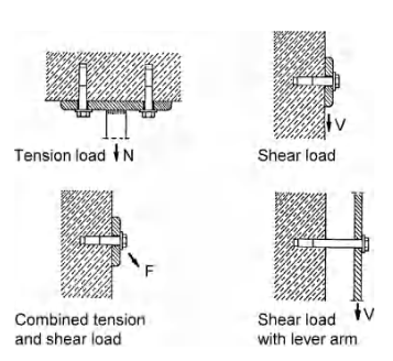 Figure: Anchorage Actions
Anchors can also be placed into bending by a standoff. This is not explicitly covered in ACI 318-19, but they do exist in cases like cladding attachments, or base plate with large grout layer.
The anchor types can be separated into 3 groups:
- Cast-In-Place
- Post-Installed Expansion
- Post-Installed Adhesive
Cast-in-place anchors rely on mechanical interlock, expansion anchors rely on friction induced by a wedge at the tip of the anchor, and epoxy anchors rely on bond or chemical interlock. Furthermore, as their name implies, installation occurs at different stage of construction.
Concrete anchors are checked with LRFD load combinations:
\[\gamma Q \leq \phi R_n\]- We use \(N\) to denote tensile demands or capacities
- We use \(V\) to denote shear demands or capacities
Here are all the tension failure modes:
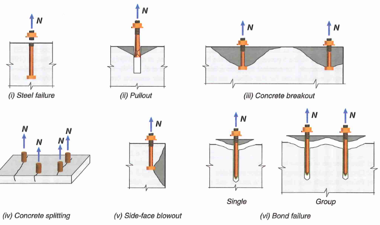 Figure: Anchor Tension Failure Modes
Here are all the shear failure modes:
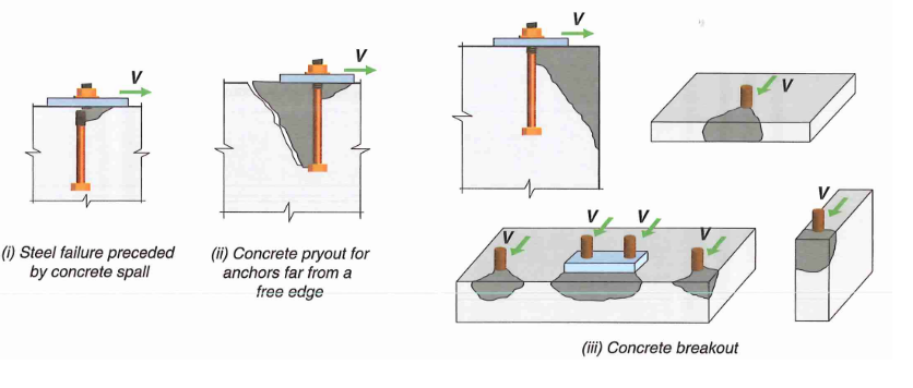 Figure: Anchor Shear Failure Modes
R17.8.3 - The typical procedure is to analyze all the various failure modes associated with shear and tension separately, and then combine the DCRs using an interaction equation at the end. The lowest tension and shear capacity shall be used below.
\[(\frac{N_{ua}}{\phi N_n})^{5/3} + (\frac{V_{ua}}{\phi V_n})^{5/3} <1.0\]17.8.3 - Alternatively, we can ignore interaction all together if shear or tension DCR is less than 20%, which gives us this trilinear interaction curve.
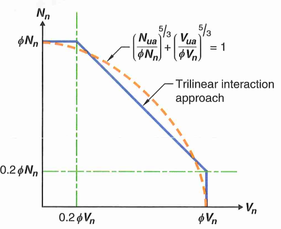 Figure: Tension-Shear Interaction Curve
Demand:
- \(N_{ua} \mbox{ or } N_{ua,i}\) = tension demand of single anchor
- \(N_{ua,g}\) = tension demand of anchor group
- \(V_{ua} \mbox{ or } V_{ua,i}\) = shear demand of single anchor
- \(V_{ua,g}\) = shear demand of anchor group
Capacities:
- \(N_{sa}\) = steel tensile strength
- \(N_{cb}\) = concrete tension breakout strength
- \(N_{cbg}\) = concrete tension breakout strength (anchor group)
- \(N_{pn}\) = anchor tension pullout
- \(N_{sb}\) = concrete side-face breakout strength in tension
- \(N_{a}\) = Tensile bond strength of adhesive anchor
- \(V_{sa}\) = steel shear strength
- \(V_{cb}\) = concrete shear breakout strength
- \(V_{cbg}\) = concrete shear breakout strength (anchor group)
- \(V_{cp}\) = concrete shear pryout strength
- \(V_{cpg}\) = concrete shear pryout strength (anchor group)
Modification Factors:
- \(\Psi_{ec,N}\) = tension breakout eccentricity factor (17.6.2.3)
- \(\Psi_{ed,N}\) = tension breakout edge distance factor (17.6.2.4)
- \(\Psi_{c,N}\) = tension breakout cracking factor (17.6.2.5)
- \(\Psi_{cp,N}\) = tension breakout splitting factor (17.6.2.6)
- \(\Psi_{c,P}\) = pullout cracking factor (17.6.3.3)
- \(\Psi_{ec,Na}\) = bond eccentricity factor (17.6.5.3)
- \(\Psi_{ed,Na}\) = bond edge factor (17.6.5.4)
- \(\Psi_{cp,Na}\) = bond splitting factor (17.6.5.5)
- \(\Psi_{ec,V}\) = shear breakout eccentricity factor (17.7.2.3)
- \(\Psi_{ed,V}\) = shear breakout edge distance factor (17.7.2.4)
- \(\Psi_{c,V}\) = shear breakout cracking factor (17.7.2.5)
- \(\Psi_{h,V}\) = shear breakout thickness factor (17.7.2.6)
2 - General Requirements
2.1 General
17.5.1.3.1 - Group Effect: Consider group effect if anchors (loaded by common element) are spaced closer than the spacing required for unreduced breakout strength. Otherwise, we can consider anchors individually.
- Tension = \(3h_{ef}\) (embed)
- Shear = \(3c_{a1}\) (edge distance)
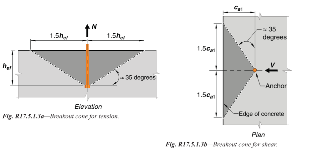
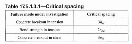 Figure: Spacing and Group Effect
17.2.4 - Lightweight Concrete Factor: Note there is an additional reduction on top of \(\lambda\)
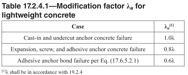 Table: Lightweight Concrete Modification Factors
17.3.1 - Max Concrete Strength: Due to lack of available test data, \(f'_c\) for calculation purposes cannot exceed 10 ksi for cast-in-place anchors, and 8 ksi for post-installed anchors.
Other requirements:
- 17.1.3 - Do not reuse post-installed anchors
- 17.1.4 - Do not use this chapter for high-cycle fatigue or impact loads
- 17.2.1 - Shear and tension demand may be calculated with an elastic analysis or a plastic analysis.
- 17.5.1.4 - Anchor strength can be established by testing using 5 percent fractile.
- 17.3.2 - Breakout equations of this chapter cannot be used if diameter exceeds 4 inches
- 17.3.3 - Adhesive anchor embed limit: \(4d_a \leq h_{ef} \leq 20d_a\)
- 17.3.3 - Screw anchor embed limit: \(5d_a \leq h_{ef} \leq 10d_a\) and larger than 1.5 in
- 17.2.2 - Adhesive anchor must be installed to concrete with curing for more than 21 days.
2.2 Seismic Design
17.10.5.3(d) and 17.10.6.3(c) - For seismic applications, concrete anchorage must be design for overstrength level forces. There are ways to avoid this by doing some more rigorous detailing, but the common practice is to just amplify anchorage demand by \(\Omega\) (see ASCE 7).
\[E_h = \Omega_o E\]- 17.10.5.1 and 17.10.6.1 - The above amplification can be ignored if earthquake portion of the total tension load in the LRFD load combination is less than 20% (i.e. most tension are permanent from dead load).
- In lieu of amplifying demand by an overstrength factor, there are other options explained in 17.10.5. In short:
- Option (a) - Follow stringent seismic detailing (e.g. material limitations, ensure concrete capacity is larger than steel, provide tension strength length, etc.)
- Option (b) - Capacity-based. Provide ductile fuses that caps the force coming into concrete anchors
- Option (c) - Design for the absolute max force that can be transmitted into the anchors by an non-yielding attachment.
17.10.5.4 - For seismic applications, concrete should be assumed to be cracked unless demonstrated otherwise.
17.10.5.4 - Tension Capacity Reduction - the following tension capacities are further reduced by 25% when subjected to seismic loads.
- Reduce tension breakout capacity (\(0.75 \phi N_{cb} \mbox{ and }0.75 \phi N_{cbg}\))
- Does not apply if breakout resisted by anchor reinforcement
- Reduce anchor pullout capacity (\(0.75 \phi N_{pn}\))
- Reduce tension side-face breakout capacity (\(0.75 \phi N_{sb} \mbox{ and }0.75 \phi N_{sbg}\))
- Reduce anchor bond capacity (\(0.75 \phi N_{a} \mbox{ and }0.75 \phi N_{ag}\))
17.10.1 - The seismic requirements of 17.10 only apply for SDC C, D, E, and F
17.10.2 - Do not use chapter 17 equations for anchors in plastic hinge zones.
2.3 Resistance Factor
17.5.3 - Resistance factors (\(\phi\)) are listed below.
- Steel Tension Failure
- \(\phi = 0.75\): Ductile steel (more common)
- \(\phi = 0.65\): Brittle steel
- Steel Shear Failure
- \(\phi = 0.65\): Ductile steel (more common)
- \(\phi = 0.60\): Brittle steel
- Tension Breakout, Bond, Side-Face Blow Out
- \(\phi = 0.70\): for cast-in anchors
- \(\phi = 0.75\): for cast-in anchors w/ anchor reinforcement
- \(\phi = 0.65\): for post-installed anchors (Category 1*). No supp. reinf.
- \(\phi = 0.55\): for post-installed anchors (Category 2*). No supp. reinf.
- \(\phi = 0.45\): for post-installed anchors (Category 3*). No supp. reinf.
- Increase factor for post-installed anchor by 0.1 if supp. reinf. is present
- Shear Breakout
- \(\phi = 0.75\): shear breakout w/ anchor reinforcement
- \(\phi = 0.70\): all other cases
- Anchor Tension Pullout
- \(\phi = 0.70\): for cast-in anchors
- \(\phi = 0.65\): for post-installed anchors (Category 1*)
- \(\phi = 0.55\): for post-installed anchors (Category 2*)
- \(\phi = 0.45\): for post-installed anchors (Category 3*)
- Shear Pryout
- \(\phi = 0.7\): All cases
- Shear Lugs
- \(\phi = 0.65\): Bearing and breakout
Definitions:
- *Anchor categories are defined in ACI 355.2 or ACI 355.4. The anchor manufacturer usually provides the appropriate category of their anchors. Category 1 indicates high reliability. Category 2 indicates medium reliability. Category 3 indicates low reliability.
- Supplementary reinforcement refers to any reinforcement within the concrete that is preventing splitting cracks. It does not need to be explicitly designed.
- Anchor reinforcement are provided specifically to help resist concrete breakout.
3 - Tensile Strength
Figure: Anchor Tension Failure Modes
3.1 Failure Mode 1 - Steel Failure
17.6.1.1 - Nominal steel strength of anchor in tension is calculated as follows:
\[N_{sa} = A_{se,N} f_{uta}\]- \(f_{uta}\) = ultimate steel rupture strength. Shall not exceed 1.9Fy or 125 ksi
- ASTM F1554 GR36: \(f_{uta} = 58 \, ksi\)
- ASTM F1554 GR55: \(f_{uta} = 75\, ksi\)
- ASTM F1554 GR105: \(f_{uta} = 125 \, ksi\)
- \(A_{se,N}\) = net cross section area in threaded region of anchor that is usually in the range of 0.7 to 0.9Ag (typically provided by manufacturer). If threaded area is not given, it can be calculated per ASME B1.1 as follows.
nt is the number of thread per inch. Thread geometry for unified coarse (UNC) can be found online. Example
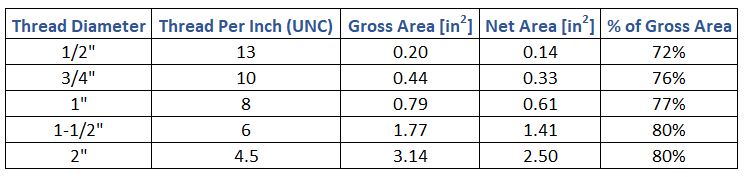 Table: Net Area of Threaded Section Estimation per UNC
Alternatively, follow the AISC 360 provisions and use gross area along with a reduced material strength.
3.2 Failure Mode 2 - Anchor Pullout
Pullout is calculated as the force at the onset of local concrete crushing at the bearing end of the anchor head. This is thought to be the beginning of a pullout failure because of the rapid decrease in stiffness afterwards. In other words, pullout capacity is purely a function of end bearing area, and is not related to embedment length (friction neglected).
17.6.3.2.1 - Pullout mechanism for expansion anchors, screws, and undercut anchors are fundamentally different and cannot be calculated per ACI 318. Instead, refer to manufacturer ESR report for suggested pullout strength.
17.6.3.2.2 - For cast-in headed studs or bolts:
\[N_{pn} = \Psi_{c,p} \times 8A_{brg}f'_c\]17.6.3.2.2 - For hooked ends anchors
\[N_{pn} = \Psi_{c,p} \times 0.9f'_c e_h d_a\]- \(A_{brg}\) is the net bearing area of the headed stud
- \(e_h\) is distance from inner surface of shaft to tip of J or L-bolt. Must be between \(3d_a\) and \(4.5d_a\)
- \(d_a\) is the diameter of anchor
- \(\Psi_{c,p}\) is the pullout cracking factor. Use 1.0 for cracked concrete (almost always), use 1.4 for uncracked concrete.
17.10.5.4 - For seismic application, reduce anchor capacity in pullout by 25%
\[0.75 \phi N_{pn}\]3.3 Failure Mode 3 - Tension Breakout
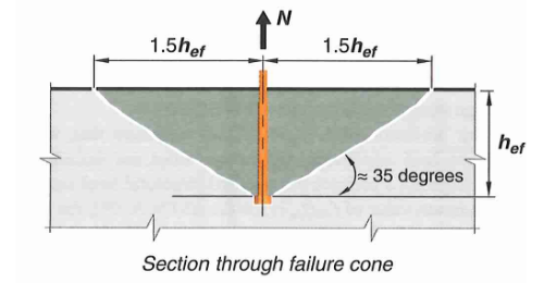 Figure: Concrete Tension Breakout Failure Cone
17.6.2.1a - For a single anchor:
\[N_{cb} = N_b \times ( \frac{A_{Nc}}{A_{Nco}} ) ( \Psi_{ed,N} \Psi_{c,N} \Psi_{cp,N})\]17.6.2.1b - For an anchor group:
\[N_{cbg} = N_b \times (\frac{A_{Nc}}{A_{Nco}}) (\Psi_{ec,N} \Psi_{ed,N} \Psi_{c,N} \Psi_{cp,N})\]That is a lot of variables. Let’s go through them one by one.
17.6.2.2 - Basic single anchor breakout capacity
This is the basic concrete breakout strength, of a single anchor, in cracked concrete. We will use this value as a starting point and apply several modification factors for other conditions.
\[N_{b} = k_c \lambda_a \sqrt{f'_c} h_{ef}^{1.5}\]where:
- \(h_{ef}\) = embedment depth
- \(k_c\) = 24 for cast-in anchors, and 17 for post-installed anchors (may be increased if proven by manufacturer)
ACI also permits a slightly less conservative equation for anchors embedded between 11 in to 25 in (17.6.2.2.3), however it becomes unconservative beyond 25 inch; making it only applicable for anchors embedded between 11” to 25”. For simplicity, it is convenient to just use equation above. But it is good to know that you can perhaps squeeze out 10 to 30 kips.
17.6.2.3 - Breakout Eccentricity Factor (\(\Psi_{ec,N}\))
This factor is unique to anchor groups. If the resultant tension on an anchor group is concentric, or if we are looking at a single anchor:
\[\Psi_{ec,N} = 1.0\]On the other hand, when a moment is applied to an anchor group, the resultant tension is not concentric meaning some anchors are more stressed in tension than others.
\[\Psi_{ec,N} = \frac{1}{1+\frac{e'_N}{1.5h_{ef}}} <=1.0\]\(e_N\) is the distance from centroid of anchor loaded in tension to the resultant tensile force.
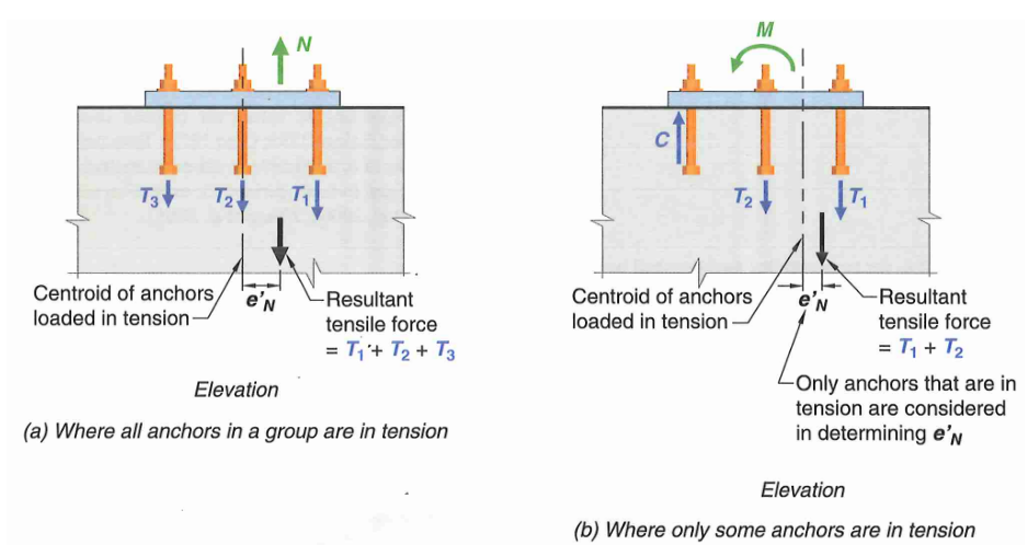 Figure: Anchor Tension Eccentricity Factors
17.6.2.4 - Breakout Edge Effect Factor (\(\Psi_{ed,N}\))
If the minimum edge distance is at least \(1.5h_{ef}\), then a full breakout cone can form and no edge reduction factor is necessary.
\[\Psi_{ed,N} = 1.0\]Otherwise, if the anchor or anchor group is close to an edge:
\[\Psi_{ed,N} = 0.7 + 0.3 \frac{ c_{a,min} }{ 1.5h_{ef} }\]\(c_{a,min}\) is the minimum edge distance.
17.6.2.1.2 - If there are 3 or more edges (less than \(1.5h_{ef}\)), such as at the end of a narrow grade beam, the effective embedment must also be reduced in all equations that involve embedment depth.
\[h_{ef} = max( c_{a,max}/1.5, s/3)\]where “s” is the maximum spacing between anchors, and \(c_{a,max}\) is the maximum edge distance that is less than \(1.5h_{ef}\)
17.6.2.5 - Breakout Cracking Factor (\(\Psi_{c,N}\))
Modification factor for cracking. Typically assume all concrete are cracked for conservatism unless more rigor is required. Cracked concrete has a modification factor of 1.0.
- \(\Psi_{c,N} = 1.0\) for cracked condition (most commonly used)
- \(\Psi_{c,N} = 1.25\) for cast-in anchors (uncracked)
- \(\Psi_{c,N} = 1.4\) for post-installed anchors (uncracked). Or use value from manufacturer ESR report.
17.6.2.6 - Breakout Splitting Factor (\(\Psi_{cp,N}\))
For cast-in anchors, or any anchors designed for cracked concrete, the splitting factor can be taken as 1.0. Since we will mostly be assuming cracked concrete, this will be the case.
\[\Psi_{cp,N} = 1.0\]For post-installed anchors designed for uncracked condition:
- \(\Psi_{cp,N} = 1.0\) if the critical edge spacing \(c_{ac}\) is met. Otherwise:
The critical edge spacing \(c_{ac}\) is required for post-installed anchors installed to uncracked condition without anchor reinforcement to prevent splitting cracks.
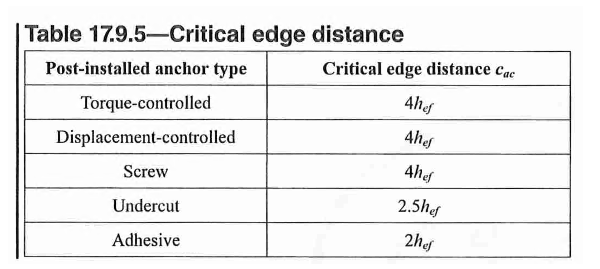 Table: Anchor Critical Edge Distance for Splitting Failure
17.6.2.1.4 - Full Projected Failure Area of Single Anchor (\(A_{Nco}\))
Based on a 35 degree breakout cone, the projected failure area is a square with side length of \(2 \times 1.5h_{ef}\). Note that the failure area is taken as a rectangle rather than an ellipse for simplicity.
\[A_{Nco} = 9h_{ef}^2\]17.6.2.1.1 - Actual Projected Concrete Failure Area (\(A_{Nc}\))
The actual breakout area must be adjusted.
For anchor group with 1 or 2 edges, this can be represented in equation form as:
\[A_{Nc} = (1.5h_{ef}+s_1+c_{a1}) \times (1.5h_{ef}+s_2+c_{a2})\]However, the projected area must not exceed \((n A_{nco})\) where n is the number of anchor in the anchor group. \(c_{a1}\) is taken as the minimum edge distance.
For anchor group with 3 or more edges, effective embedment depth has to be reduced per 17.6.2.1.2. See figure below for example breakout area calculation. In essence, the breakout cone will extend \(1.5h_{ef}\) orthogonally beyond the outermost anchor unless interrupted by an edge.
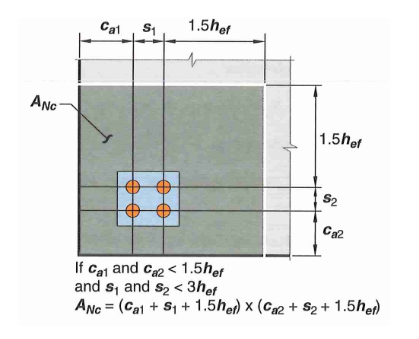 Figure: Concrete Breakout Area Example
17.10.5.4 - For seismic application, reduce tension breakout capacity by 25%
\[0.75 \phi N_{cb}\]3.4 Failure Mode 3a - Breakout Anchors
In many cases, it may be impossible to rely on concrete alone for breakout capacity. In these cases, we may provide anchor reinforcements.
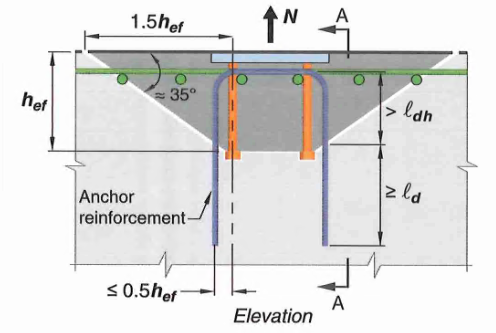 Figure: Concrete Tension Breakout - Anchor Reinforcements
17.5.2.1 - Breakout capacity with anchors is equal to the strength of all anchor reinforcements that can be developed on both ends of the splitting plane. \(\phi N_{cbg} = \phi f_y A_s\)
- \(f_y\) is the yield strength of anchor reinforcement
- \(A_s\) is the total steel area of anchor reinforcement
- Use \(\phi = 0.75\) per 17.5.3
Detailing requirements:
- Reinforcement must be developed on both sides of the breakout line
- Anchor rebar should be placed as close to the resultant tension as possible. No more than 0.5h_{ef} from anchor centerline
- Available research data is based on #5 bars. Bend radii of larger bars may reduce effectiveness. Bar larger than #6 not recommended but not prohibited by code either.
3.5 Failure Mode 4 - Side Face Blowout
This failure mode is only applicable for anchors near an edge.
17.6.4.1 - For single headed anchor with \(h_{ef} > 2.5 c_{a1}\):
\[N_{sb} = 160 c_{a1} \sqrt{A_{brg}} \lambda_a \sqrt{f'_c}\]17.6.4.1.1 - if \(c_{a2} < 3c_{a1}\), then multiply the above equation by the factor:
\[0.25(1+ \frac{c_{a2}}{c_{a1}})\]- \(A_{brg}\) is the net bearing area of the headed stud
- \(c_{a1}\) is the edge distance in the direction of applied shear. If no shear is applied, use the minimum edge distance
- \(c_{a2}\) is the edge distance perpendicular to \(c_{a1}\)
- In the equation above, \(\frac{c_{a2}}{c_{a1}}\) should be between 1.0 to 3.0
17.6.4.2 - For head anchor group with \(h_{ef} > 2.5 c_{a1}\) and anchor spacing along the edge \(s< 6c_{a1}\):
\[N_{sbg} = (1+ \frac{s}{6c_{a1}}) N_{sb}\]Only the anchors close to the edge (\(c_{a1}<0.4h_{ef}\)) should be considered.
17.10.5.4 - For seismic application, reduce side face blowout capacity by 25%
\[0.75 \phi N_{sb}\]3.6 Failure Mode 5 - Epoxy Anchor Bond Failure
This failure mode is only applicable for adhesive anchors.
Because adhesive anchor bond capacity is highly product dependent. You’ll likely need to refer to the manufacturer’s product catalog and ESR report. It may be easier to use their proprietary software for the design of these anchors.
17.6.5.1a - For single adhesive anchor:
\[N_a = N_{ba} \times (\frac{A_{Na}}{A_{Nao}})(\Psi_{ed,Na} \Psi_{cp,Na})\]17.6.5.1b - For group of adhesive anchors:
\[N_{ag} = N_{ba} \times (\frac{A_{Na}}{A_{Nao}})(\Psi_{ec,Na} \Psi_{ed,Na} \Psi_{cp,Na})\]Again, this is a lot of variables. Let’s go through them one by one.
17.6.5.2 - Basic Single Anchor Bond Strength (\(N_{ba}\))
The basic bond strength of a single adhesive anchor in tension in cracked concrete is:
\[N_{ba} = \lambda_a \tau_{cr} \pi d_a h_{ef}\]where \(t_{cr}\) is the allowable bond stress provided by the manufacturer. Alternatively, we can use the minimum bond stress value provided in 17.6.5.2.5:
- \(\tau_{cr} = 200 psi\), for outdoor condition cracked
- \(\tau_{cr} = 300 psi\), for indoor condition cracked
- \(\tau_{uncr} = 1000 psi\), for indoor condition uncracked
- \(\tau_{uncr} = 600 psi\), for outdoor condition uncracked
17.6.5.2.5 - If anchor is under sustained tension, multiply \(t_{cr}\) by a factor of 0.4
17.6.5.2.5 - If anchor is under earthquake induced tension, multiply \(t_{cr}\) by a factor of 0.8
17.6.5.1.2 - Bond Breakout Influence Area (\(A_{Nao}, A_{Na}\))
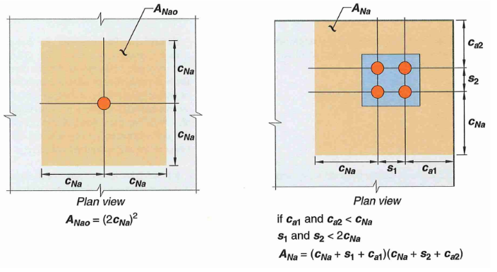 Figure: Concrete Breakout Area For Adhesive Anchors
The breakout influence area is fundamentally different than typical anchors. Rather than \(1.5h_{ef}\), we need to calculate the projected length \(c_{Na}\) which is a function of uncracked bond stress:
\[c_{Na} = 10d_a \sqrt{\frac{\tau_{uncr}}{1100}}\]Then the full breakout area can be calculated as:
\[A_{Nao} = (2c_{Na})^2\]Similarly to before, the projected breakout cone extends a length of \(c_{Na}\) (rather than \(1.5h_{ef}\)) unless interrupted by an edge. Refer to figure above for a sample calculation.
17.6.5.3 - Bond Eccentricity Factor (\(\Psi_{ec,Na}\))
Similar to the typical breakout eccentricity factor, just swap \(1.5h_{ef}\) and \(c_{Na}\).
\[\Psi_{ec,Na} = \frac{1}{(1-\frac{e'_N}{C_{Na}})} <= 1.0\]17.6.5.4 - Bond Edge Effect Factor (\(\Psi_{ed,Na}\))
Similar to the typical breakout edge factor, just swap \(1.5h_{ef}\) and \(c_{Na}\). If the minimum edge distance is at least \(c_{Na}\), then a full breakout cone can form and no edge reduction factor is necessary. Otherwise, if the anchor or anchor group is close to an edge:
\[\Psi_{ed,Na} = 0.7 + 0.3 \frac{ c_{a,min} }{ c_{Na} }\]17.6.5.5 - Bond Splitting Factor (\(\Psi_{cp,Na}\))
Similar to the typical splitting factor, just swap \(1.5h_{ef}\) and \(c_{Na}\). For anchors designed for cracked concrete, the splitting factor can be taken as 1.0. Since we will mostly be assuming cracked concrete, this will be the case.
For anchors designed for uncracked condition:
- \(\Psi_{cp,Na} = 1.0\) if the critical edge spacing \(c_{ac}\) is met, otherwise:
Other Modification Factors
17.5.2.2 - If adhesive anchors are to resist sustained tension, then the capacity must be reduced by 45%.
\[0.55 \phi N_{sa}\]17.10.5.4 - For seismic application, reduce bond capacity by 25%.
\[0.75 \phi N_{sa}\]As you can probably tell already, adhesive anchors are terrible under sustained tension. Reduction factor from 17.5.2.2 and 17.6.5.2.5 stack resulting in a reduction of almost 80%(0.55*0.4=0.22).
4 - Shear Strength
Figure: Anchor Shear Failure Modes
4.1 Failure Mode 1 - Steel Failure
17.7.1.2b - For cast-in headed bolts and anchors:
\[V_{sa} = 0.6* A_{se,V} f_{uta}\]17.7.1.2a - Cast-in headed stud anchors can achieve slightly higher capacity due to fixity provided by the welds between plate and anchor:
\[V_{sa} = A_{se,N} f_{uta}\]17.7.1.2c - For post-installed anchors, look for ESR report from manufacturer
where:
- \(f_{uta}\) = ultimate steel rupture strength. Shall not exceed 1.9Fy or 125 ksi
- ASTM F1554 GR36: \(f_{uta} = 58 \, ksi\)
- ASTM F1554 GR55: \(f_{uta} = 75\, ksi\)
- ASTM F1554 GR105: \(f_{uta} = 125 \, ksi\)
- \(A_{se,V}\) = net cross section area in threaded region of anchor that is usually in the range of 0.7 to 0.9Ag. If threaded area is not given, it can be calculated per ASME B1.1 as follows.
Table: Net Area of Threaded Section Estimation per UNC
Alternatively, follow the AISC 360 provisions and use gross area along with a reduced material strength.
17.7.1.2.1 - Grout Pads: for anchors used with built-up grout pad (as is common in base plate connections), the calculated steel shear strength must be reduced by 0.8. The 20% reduction above is much less conservative than the European equivalent ETAG Annex C, or the AISC provisions assuming anchor flexure.
4.2 Failure Mode 1a - Anchor Bending (AISC)
ACI 318 is silent about shear attachment with lever arm, commonly seen in cladding attachments. In seismic designs, the grouts under base plates is also sometimes treated as shear with lever arm due to spalling.
According to AISC Design Guide 1 Section 4.3.3, design anchors for the combined shear stress and tensile stress due to bending:
Shear stress: \(f_v = \frac{V_{rod}}{A}\)
Tension stress due to bending: \(f_t = M_{rod}/Z\)
Tension due to net uplift: \(f_t = \frac{P_{rod}}{A}\)
Combined interaction DCR: \((\frac{f_v}{\phi F_{nv}})^2 + (\frac{f_t}{\phi F_{nt}})^2 \leq 1.0\)
Where:
- \(V_{rod}\) = shear demand on a single anchor rod
- \(M_{rod}\) = moment demand on a single anchor rod = \(V_{rod} \times L_b\)
- \(L_b\) = bending lever arm (e.g. grout thickness)
- \(P_{rod}\) = axial demand on a single anchor rod
- \(A\) = gross area of anchor (unreduced by threads)
- \(Z\) = plastic section modulus of rod = \(d_a^3/6\)
- \(d_a\) = diameter of anchor rod
- \(\phi\) = 0.75 for shear and tension in AISC 360 section J
- \(F_{nt}\) = effective anchor shear stress capacity per AISC 360 section J
- ASTM F1554 GR 36 Type N: 26.1 ksi
- ASTM F1554 GR 55 Type N: 33.8 ksi
- ASTM F1554 GR 105 Type N: 56.3 ksi
- \(F_{nv}\) = effective anchor tension stress capacity per AISC 360 section J
- ASTM F1554 GR 36: 43.5 ksi
- ASTM F1554 GR 55: 56.3 ksi
- ASTM F1554 GR 105: 93.8 ksi
4.3 Failure Mode 1b - Anchor Bending (ETAG 001 Annex C)
Rather than imposing additional flexural stress onto the anchors, the additional bending induced by the eccentricity is converted to a reduced shear capacity
\[V_S^M = \alpha_M M_s / L_b\]Where:
- \(M_s\) is the moment capacity of one anchor rod and can be calculated as shown. Note the use of ultimate material strength Fu, as well as reduction based on tension DCR:
- \(L_b\) is the stand off eccentricity as shown below to center of fixture plate. It should be adjusted for a spalling distance of \(0.5d_a\) unless clamped to prevent spalling
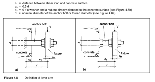 Figure: Lever Arm Distance
- \(\alpha_M\) adjusts the curvature assumption and ranges from 1 for single curvature bending, to 2 for double curvature bending. The assumption of single curvature bending is appropriate if the fixture can rotate freely which is not the case for base plates. Double curvature can also be achieved by clamping both sides of the plate with nuts and washers
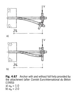 Figure: Single and Double Curvature
Comparison of ACI Treatment with Grout Layer According to ACI 318 17.7.1.2.1 shear capacity of anchor in grout pad (regardless of thickness of grout) shall be reduced by 20%. However, this is not very conservative compared to the European equivalent standards by at least a factor of 3.
The conservatism from the European code primarily comes from the anticipation that thicker grout pads may spall, leading the front anchors transferring shear primarily via bending. Section 14.4.5.2.2 of the Eligehausen textbook provides the recommendation that lever arm may be neglected only if all the following conditions are satisfied:
- If grout thickness is less than d_a/2
- If contact length of anchor to base plate is at least 0.5 t_p
- Not using oversized holes
For comparison purposes: a 1.5” diameter, GR 55 anchor rod, with 3” lever arm has the following factored capacities (per anchor rod):
- ACI 318-19: 34 kips
- AISC 360: 7.8 kips
- ETAG 001 Annex C: 13 kips (assuming tension DCR = 0)
4.4 Failure Mode 2 - Shear Breakout
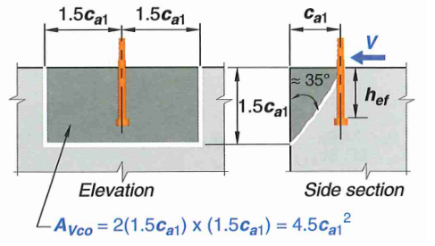 Figure: Concrete Shear Breakout Failure Cone
17.7.2.1a - For a single anchor:
\[V_{cb} = V_b \times ( \frac{A_{Vc}}{A_{Vco}} ) ( \Psi_{ed,V} \Psi_{c,V} \Psi_{h,N})\]17.7.2.1b - For an anchor group:
\[V_{cbg} = V_b \times (\frac{A_{Vc}}{A_{Vco}}) (\Psi_{ec,N} \Psi_{ed,N} \Psi_{c,N} \Psi_{h,N})\]17.7.2.1c - Note that shear breakout may also occur for shear acting parallel to an edge. The breakout capacity in these situations is determined by assuming load acting perpendicular to the edge, then multiply by 2. Edge factor should be taken as 1 in these situations.
\[V_{cb,parallel} = 2 \times V_{cb}\]The equations are essentially the same as tension breakout with a few subscript changes. Let’s go through them one by one.
17.7.2.2 - Basic single anchor shear breakout capacity
17.7.2.2.1 - This is the basic concrete breakout strength, of a single anchor, in cracked concrete. We will use this value as a starting point and apply several modification factors for other conditions. The basic capacity shall be the minimum of:
\[V_{b} = (7 (\frac{l_e}{d_a}) ^{0.2} \sqrt{d_a}) \times \lambda_a \sqrt{f'_c} (c_{a1})^{1.5}\] \[V_{b} = (9) \times \lambda_a \sqrt{f'_c} (c_{a1})^{1.5}\]where:
- \(l_e\) is the bearing length and shall be equal to \(h_{ef}\) for anchor with constant stiffness over the full length and shall not exceed \(8d_a\)
- \(l_e = 2d_a\) for torque controlled expansion anchors with a distance sleeve separated from expansion sleeve
17.7.2.2.2 - The constant “7” in the first equation above may be increased to 8 should the following conditions be satisfied:
- Anchor is continuously welded to a steel attachment plate
- Anchor spacing is at least 2.5 in
- Corner reinforcement provided if \(c_{a2} <= 1.5h_{ef}\)
- attachment plate has thickness greater than \(0.5d_{a}\) or 3/8 in
17.7.2.3 - Shear Breakout Eccentricity Factor (\(\Psi_{ec,V}\))
This factor is unique to anchor groups. If the resultant shear on an anchor group is concentric, or if we are looking at a single anchor:
\[\Psi_{ec,V} = 1.0\]On the other hand, when a moment is applied to an anchor group, the resultant tension is not concentric meaning some anchors are more stressed than others.
\[\Psi_{ec,V} = \frac{1}{1+\frac{e'_V}{1.5c_{a1}}} <=1.0\]\(e_V\) is the distance from centroid of anchor loaded in shear to the resultant shear force.
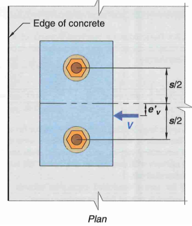 Figure: Anchor Tension Eccentricity Factors
17.7.2.4 - Breakout Edge Effect Factor (\(\Psi_{ed,V}\))
Unlike edge factor for tension, shear breakout is always near an edge. In this case, we have to adjust for the edge parallel to shear force \(c_{a2}\) (if any)
If the \(c_{a2} > 1.5c_{a1}\) then no reduction is necessary.
\[\Psi_{ed,V} = 1.0\]Otherwise:
\[\Psi_{ed,V} = 0.7 + 0.3 \frac{ c_{a2} }{ 1.5c_{a1} }\]17.7.2.5 - Breakout Cracking Factor (\(\Psi_{c,V}\))
Modification factor for cracking in shear breakout depends on rebar condition near the edge:
- \(\Psi_{c,N} = 1.0\) no supplemental reinforcement parallel to edge (or smaller than #4)
- \(\Psi_{c,N} = 1.2\) reinforcement exists parallel to edge and is #4 or larger
- \(\Psi_{c,N} = 1.4\) reinforcement exists plus sitrrups enclose the supplemental reinf. with spacing not more than 4”
17.7.2.6 - Member Thickness Factor (\(\Psi_{h,V}\))
Breakout capacity in shear is not directly proportional to member thickness (\(h_a\)). This factor accounts for this effect:
\[\Psi_{h,V} = \sqrt{\frac{1.5c_{a1}}{h_a}}\]17.7.2.1.3 - Full Projected Failure Area of Single Anchor (\(A_{Vco}\))
Based on a 35 degree breakout cone, the projected failure area is a rectangle with side length of \((2)1.5c_{a1}\) and depth of \(1.5c_{a1}\)
\[A_{Vco} = 4.5c_{a1}^2\]17.7.2.1.4 - If anchors are located at varying distance welded to an attachment plate. Then the strength can be calculated based on the furthest anchors neglecting other rows of anchors. Refer to the figure below for a better illustration.
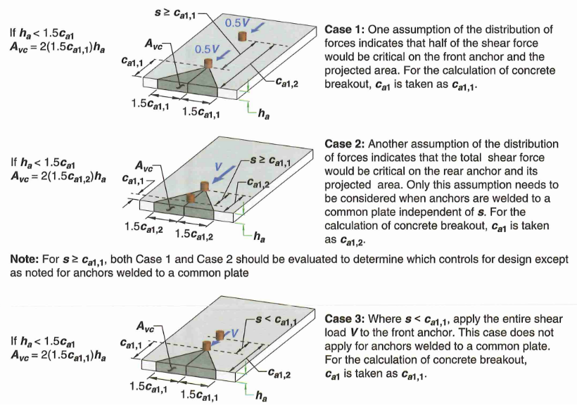 Figure: Difference Cases to Check For Anchor Groups
17.7.2.1.1 - Actual Projected Concrete Failure Area (\(A_{Vc}\))
The actual breakout area must be adjusted depending on the perpendicular edge or anchor groups. However, the projected area must not exceed \((n A_{Vco})\) where n is the number of anchor in the anchor group. See figure below for some example calculations.
- Essentially the breakout depth will be equal to \(1.5c_{a1}\) subject to limitation of member thickness
- The width of breakout extends \(1.5c_{a1}\) on either end unless interrupted by an edge
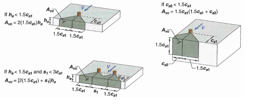 Figure: Concrete Breakout Area Example
17.7.2.1.2 - If the anchor is located in a narrow section where both this member thickness, and \(c_{a2}\) are less than \(1.5c_{a1}\), then \(c_{a1}\) must be adjusted as the maximum of:
- Larger edge distance: \(c_{a2} / 1.5\)
- Member thickness: \(h_a / 1.5\)
- \(s/3\) where s is the maximum spacing perpendicular to direction of shear
4.5 Failure Mode 2a - Breakout Anchors
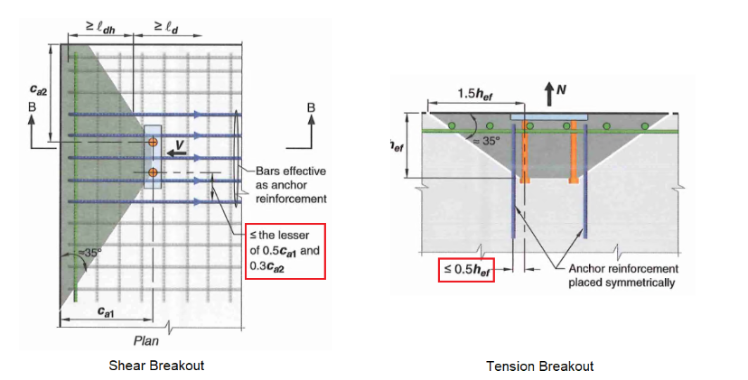 Figure: Concrete Shear Breakout - Anchor Reinforcements
In many cases, it may be impossible to rely on concrete alone for breakout capacity. In these cases, we may provide anchor reinforcements.
17.5.2.1 - We may take breakout capacity as equal to the strength of all anchor reinforcements that can be developed on both ends of the splitting plane. \(\phi V_{cbg} = \phi f_y A_s\)
- \(f_y\) is the yield strength of anchor reinforcement
- \(A_s\) is the total steel area of anchor reinforcement
- Use \(\phi\) = 0.75 per 17.5.3
The following detailing requirements must be met:
- Reinforcement must be developed on both sides of the breakout line
- For shear breakout, anchor should be placed as close to top of slab as possible while basically touching the anchors.
- For shear breakout, anchor rebar are effective within a width equaling to min(0.5c_{a1},0.3c_{a2})* Available research data is based on #5 bars. Larger bend radii of larger bars may reduce effectiveness. Bar larger than #6 not recommended but not prohibited by code either.
4.6 Failure Mode 3 - Anchor Pryout
17.7.3 - Concrete pry out strength is simply calculated as a multiple of tension breakout strength
(a) For a single anchor:
\[V_{cp} = k_{cp} N_{cp}\](b) For an anchor group:
\[V_{cpg} = k_{cp} N_{cpg}\]Where:
- \(k_{cp}\) = 1.0 for embedment less than 2.5 inches, or 2.0 for embedment larger than or equal to 2.5 inches
- \(N_{cp},N_{cpg}\) = tension breakout capacity for cast-in/post-installed or adhesive anchors
4.7 Failure Mode 4 - Shear Lugs
General
Shear lugs are rectangular plates, or steel shape composed of plate-like elements welded to base plate elements. They resist shear via a bearing mechanism.
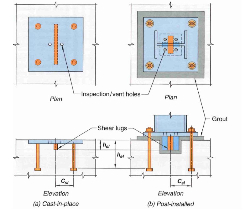 Figure: Shear Lugs
17.11.1.1.2 - Minimum of four anchor rods shall be provided when using a shear lug
17.11.1.1.3 - The use of shear lugs enable separation of shear and tension design, provided that the anchors are not welded to the base plate. In other words, the lugs resist shear and the anchor rods resist tension. If anchors are rigidly connected, displacement compatibility implies a certain amount of shear should be resisted by the anchor rods which must be accounted for. The applied shear that each anchor carries is calculated as shown:
- Anchor not welded or rigidly attached to base plate:
- Anchor welded to base plate (\(A_{ef,sl}\) is the bearing area of shear lug:
17.11.1.1.8 - The following dimensional constraints must be satisfied in order to reduce interaction between breakout and anchor in tension.
- anchor embed depth to shear lug depth (\(h_{ef}/h_{sl} >= 2.5\))
- anchor embed depth to distance between shear lug and centerline of anchor in tension (\(h_{ef}/c_{sl} >= 2.5\))
17.11.1.1.9 - Moment due to shear lug shall be added to the overall design moment in the base plate
Bearing Capacity
17.11.2.1 - Bearing capacity of shear lug can be calculated as:
\[V_{brg,sl} = 1.7 f'_c A_{ef,sl} \Psi_{brg,sl}\]17.11.2.2 - \(\Psi_{brg,sl}\) is the bearing factor which accounts for effect of axial load:
- No axial load
- Net tension (Pu is -ve)
- Net compression (Pu is +ve)
17.11.2.1.1 - \(A_{ef,sl}\) is the effective bearing area an is concisely illustrated in the figure below
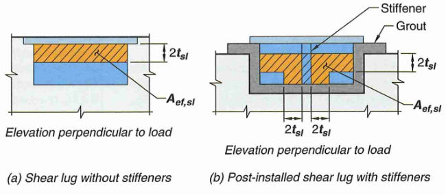 Figure: Shear Lug Bearing Area
Breakout Capacity
17.11.3.1 - Shear breakout capacity of shear lugs are calculated in the exact same way as section 4.3 of this article. The breakout area is summarized in the figure below
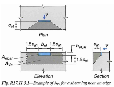 Figure: Shear Lug Shear Breakout Area
Some notes regarding shear lug breakout:
- \(c_{a1}\) is taken as the distance between edge to face of shear lug
- The basic breakout strength is taken as the ceiling value: \(V_{b} = (9) \times \lambda_a \sqrt{f'_c} (c_{a1})^{1.5}\)
- For shear parallel to edge, follow the same recommendation provided in section 4.3 of this article. Use \(c_{a1}\) as distance from edge to center of shear lug. Take eccentricity factor as 1.0
5 - Spacing and Edge Distances
There is another failure mode where concrete splits around the anchor zone; however, rather than calculating a splitting capacity, concrete splitting is precluded by meeting specific development, cover, spacing, edge distance requirements.
Most manufacturer ESR report will provide this information which will supersede the generic limits provided below.
17.9.2 - in general, try to have spacing of at least \(6d_b\) and edge distance at least \(8d_b\)
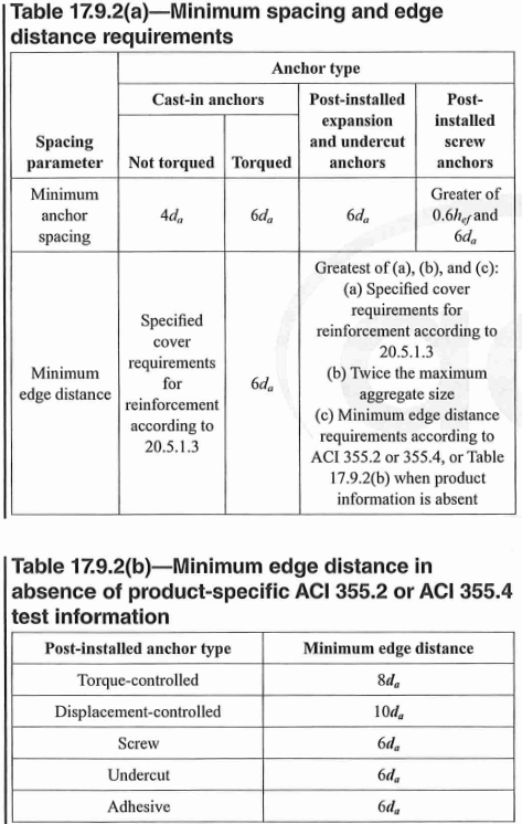 Table: Splitting Failure Spacing and Edge Distance Requirements
17.9.5 - For design of post-installed anchor in uncracked concrete without supplemental reinforcement, the critical edge spacings are very conservative and are listed below.
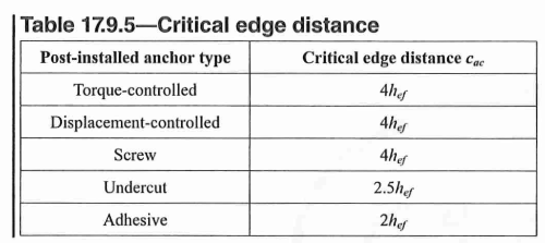 Table: Critical Edge Distance
17.9.4 - Effective embedment of post-installed anchors should not exceed 2/3 of slab depth to prevent blowout on the opposite side. Note this does not apply to epoxy or cast-in anchors.
\[h_{ef} \leq 3/4 h_{slab}\]