Primer: Base Plate Design
“Primers” are my personal notes on various technical topics in structural engineering. Building codes are dense and voluminous, sometimes written in legalese rather than in sentences that can be easily understood. I write these “Primer” so I can gather, organize, and condense technical topics I encounter as an engineer. Please understand I made these for myself. Reader discretion is advised. No warranty is expressed or implied by me on the validity of the information presented herein.
- 1.0 Introduction and Procedure
- 2.0 Preliminary Design and Detailing
- 3.0 Analysis Model and Assumptions
- 4.0 Base Plate Classification and Load Distribution
- 5.0 Failure Mode 1 - Concrete Bearing
- 6.0 Failure Mode 2 - Base Plate Bending
- 7.0 Failure Mode 3 - Anchor Rod Tension
- 8.0 Failure Mode 4 - Anchor Rod Pullout
- 9.0 Failure Mode 5 - Concrete Tension Breakout
- 10.0 Failure Mode 6 - Concrete Side Face Blowout
- 11.0 Treatment of Shear Demand
- 12.0 Option 1 - Base Plate Design With Shear Lugs
- 13.0 Option 2 - Base Plate Design Without Shear Lugs
- Appendix A - Base Rotational Spring Stiffness
1.0 Introduction and Procedure
Base plates are usually the interface between two different materials (namely steel and concrete). As a result, although technically straight-forward, a comprehensive design considering all potential failure mode can be quite lengthy and tedious.
This goal of this article is to present the theoretical background behind base plate design, from load distribution to the various limit state. By the end, you’ll hopefully have enough know-how to build your own base plate calculation tool, or gain enough technical knowledge such that you can have more confidence using existing tools.
This article is a combination of fundamentals you’ll find in the references below, as well as commentaries from my own experience.
- AISC Design Guide 1
- AISC 360-16
- ACI 318-19 (chapter 17)
1.1 Procedure
- Determine axial, shear, and moment demand (Pu, Vu, Mu)
- Classify base plate type (small moment or large moment)
- Determine load distribution (anchor force and bearing stress)
- Check the following limit states:
- Check concrete bearing (ACI 318)
- Check base plate bending (AISC 360)
- Check anchor rod tensile rupture (AISC 360, ACI 318)
- Check anchor rod pullout (ACI 318)
- Choose how shear demand is resisted
- For base plate with shear lugs, tension and shear design can be decoupled:
- Check shear lug bearing (ACI 318)
- Check shear lug bending (ACI 318)
- Check shear lug edge breakout (ACI 318)
- For base plate without shear lug, need to check tension + shear interaction
- Check anchor rod shear rupture (AISC 360, ACI 318, ETAG 001)
- Check anchor rod shear pryout (ACI 318)
- Check AISC combined tension + shear interaction (AISC 360)
- Check ACI combined tension + shear interaction (ACI 318)
- Some other limit states:
- Check concrete tension breakout (ACI 318)
- Check concrete side face blowout (ACI 318)
2.0 Preliminary Design and Detailing
2.1 Preliminary Sizes and Edge Distance Requirements
Base plate footprint (width-B, depth-N) should be sized satisfy:
- AISC 360-16 Table J3.4 minimum edge distances requirements
- Providing enough clearance for anchor rod washers and holes
The recommended hole dimensions are shown in the table below. Notice that base plate holes are even larger than OVS holes!
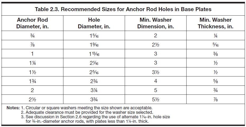 Figure 1: Recommended Anchor Rod Hole Dimension from DG1
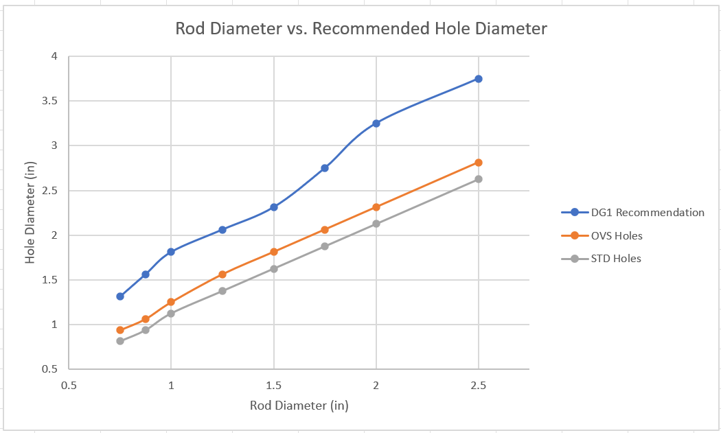 Figure 2: Recommended Anchor Rod Hole Dimension Comparison
Base plate holes are huge! This is because constructing them is a pain. Anchor rods are typically cast first into the foundation element, then base plates are then lowered onto the rods. Rods are often slightly off, or bent/damaged during pour. Hence the extra huge holes.
We need to take into account the worst case of a misaligned anchor rod + washer dimension. See illustration below.
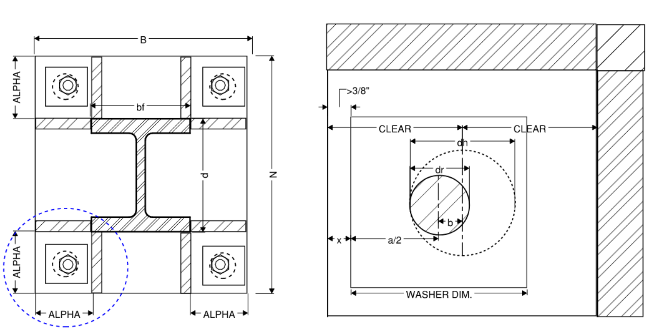 Figure 3: Misaligned Rod + Washer Dimension
The table below provides recommended extension lengths based on the worst case of 1.) minimum edge distance and 2.) providing enough clearance for 5/16” weld around washer. Let:
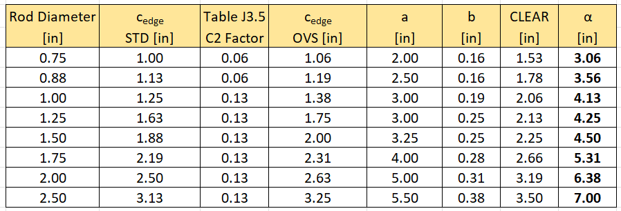 Figure 4: Minimum Edge Distances and Recommended Base Plate Size
In summary, here are my recommendations for preliminary base plate dimensions given a chosen anchor rod diameter.
Recommended Width - B
Knowing the column width (
Recommended Depth - N
Knowing the column depth (
Recommended Thickness - t
Required thickness can be approximated using a simple cantilever beam model with uniform load + some fudge factors for conservatism.
For columns with minimal moment demand:
For columns with significant moment demand, replace
Recommended Anchor Rod
There are three anchor rod grades commonly used.
- ASTM 1554 GR 36 (Fu = 58 ksi)
- ASTM 1554 GR 55 (Fu = 75 ksi)
- ASTM 1554 GR 105 (Fu = 125 ksi)
There are plenty of options for anchor rod diameter but try to stick to diameters listed in Figure 2. Pick diameter in 1/4” increments. Typically I have three buckets:
- Light: 0.75 in
- Medium: 1.25 in
- Heavy: 2.0 in
Do not specify different grade anchors with the same diameter. It gets confusing on-site.
Picking the appropriate anchor rod is somewhat more iterative, but a good starting point would be to do the following:
-
For gravity columns and columns with very small moment and no net uplift, it is probably okay to go with a smaller anchor rods (say 1” GR 36). These base plates are categorized as “small moment” and the anchor rods don’t experience much, if any, tension demand. They might need to resist some shear if no shear lug is provided. But since the moment is small, shear is likely small too.
-
For columns classified as “large moment” or having net uplift, we can use the following expression to get somewhere in the ball park. Select anchor grade (see Fu above), number of anchor rods (
2.2 Other Things to Consider Before You Begin
Rather than specifying an unique designs for every single base plate in the building, the better approach is to come up with reasonable number of base plate design “groups” from the outset. This will save you a lot of trouble later on when you put your design on the drawings.
No one wants to build a building where every base plate is different. We need to shrink our number of design to a manageable amount anyways. Therefore, create a base plate design schedule first. Something like below from the outset:
 Figure 5: Create A Base Plate Schedule From The Outset
3.0 Analysis Model and Assumptions
3.1 Analysis Model And Load Combinations
Base reactions can be extracted from any analysis software. We are interested in the axial demand, shear demand, and moment demand from the most critical load combination.
Column base connections are technically designed to remain elastic. So we need to use the appropriate overstrength load combinations:
The equation above is just for reference purposes. Ideally, your design combination is an envelope of many other load combinations that takes into account:
- 100%-30% seismic force directional combinations if applicable (e.g. 100X+30Y, 30X+100Y, -30X+100Y, …)
- Accidental mass eccentricities
- Other assumed loading configurations
For Moment Demand, AISC 341-16 Section D.2.6c specifies the required flexure demand as the minimum of expected plastic moment capacity of the column or moment demand from analysis model using overstrength load combination (the second one is usually smaller and thus governs):
If there are shear lugs, an additional moment is generated by the eccentric bearing. Refer to the shear lug section for more information.
For Shear Demand, AISC 341-16 Section D.2.6b specifies the required shear demand as the minimum of expected shear due to double curvature of the column or shear demand from analysis model using overstrength load combination.
Furthermore, there is a minimum design shear that is often missed. This value may be refined using a story compatibility analysis assuming drift of 0.025H
3.2 Loading Scenario
Furthermore, we need to consider two “load scenarios”. A high compression case, and a uplift (or low compression) case.
- High compression case:
- Low compression/uplift case:
The need to evaluate uplift is self-explanatory. However, even if the column never experiences uplift, it is important to look at low-compression scenario because base plate classification is a function of axial demand. In other words, under lower compression, the base plate may change from small eccentricity where anchor rods don’t experience tension to large eccentricity case where they do.
Since demands are enveloped, it is difficult to say low or high axial demand necessarily corresponds to high or low shear or moment. The easiest and most conservative approach is to just always extract the absolute maximum value for shear and moment.
3.3 Fixed Base or Pin Base Model?
ALthough it is always easier to design for pinned condition, make sure your jurisdiction allows for such assumption.
- HCAI and DSA projects will probably require rigorous justification if you want to use pinned model
- As your moment frame system gets bigger, it is tough to justify full pinned condition without special detailing
- Behavior of pinned and fixed based moment frames are quite different. So it’s probably a good idea to get base fixity sorted out early
- While it is more “correct” to design for at least some moment, the resulting base plate could be quite large.
The reality is probably somewhere in between (i.e. partial fixity). Refer to the appendix for some discussion on how to calculate a rotational spring stiffness.
4.0 Base Plate Classification and Load Distribution
4.1 Base Plate Design Classification
Base plates can be classified into two categories:
- Small moment - resultant is within kern (column is stable without any tie down force from anchors)
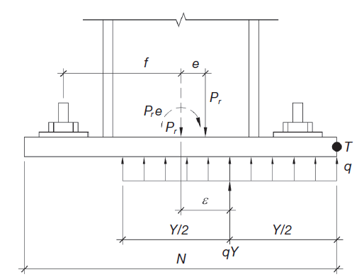 Figure 6: Small Moment Base Plate
- High moment - resultant outside kern
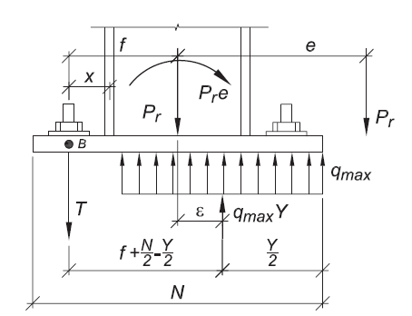 Figure 7: Large Moment Base Plate
The dividing line between the two categories is known as the critical eccentricity.
Although we use the term kern above, it should be noted that AISC Design Guide 1 suggests a less conservative approach:
- Elastic assumption (
- Think adding rectangles and triangles (P/A - M/S)
- Plastic assumption (
- Think in terms of Net moment = overturning moment - restoring moment. If restoring moment is larger, anchor rods are numerically not needed for equilibrium. In other words, even if part of the base plate is not in contact anymore, fixture is still overall stable without relying on anchor rods.
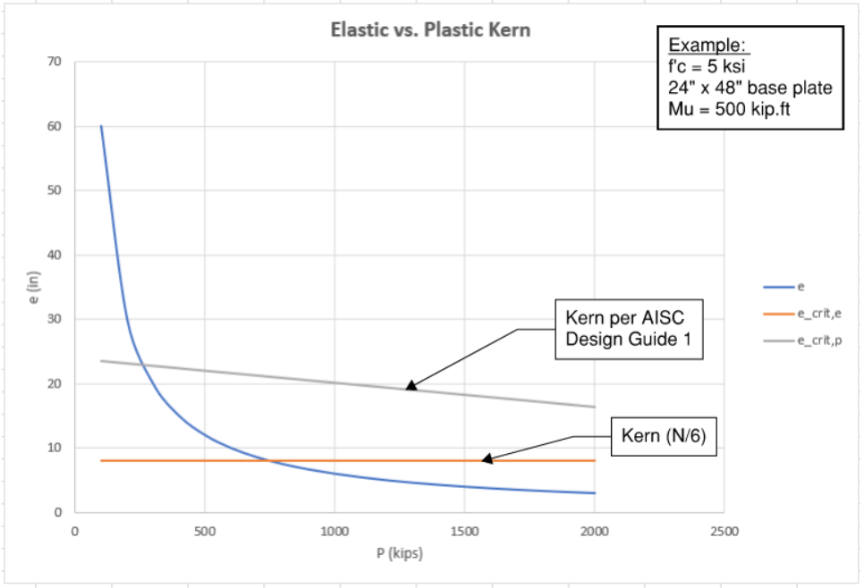 Figure 8: Kern Comparison
For example, in the chart above, we are looking at a 24” x 48” base plate with moment demand of 500 kip.ft.
- Using “elastic” kern, “small moment” if P > 750 kips
- Using “plastic” kern, “small moment” if P > 250 kips (3x lower!)
The logic behind plastic stress distribution is as follows:
- Moment increases, thus eccentricity increases (e = M/P) which shifts our downward pointing arrow shifts more and more to the edge
- Bearing contact area decreases, bearing stress increases (i.e. down arrow and up arrow coincide for equilibrium)
- Bearing stress is limited to the capacity of the concrete. Eventually the reaction force resultant can no longer follow (i.e satisfy equilibrium) without exceeding bearing capacity of concrete
- At this point, anchor rods are engaged for equilibrium (transition from figure 6 to 7)
Procedure
-
Calculate eccentricity (remember to convert moment from kip.ft to kip.in)
-
Calculate concrete bearing capacity. See section 3 for more info.
-
Normalize bearing stress from ksi to kip/in along depth of base plate
-
Calculate critical eccentricity (N is base plate depth)
- Refer to section 2.5 for small moment case; refer to section 2.6/2.7 for large moment case.
- Base plate subjected to axial tension (T+M) are always classified as large moment!
4.2 Small Moment Base Plate (
Design of small moment base plate is easy! No anchor rod tension to worry about which means we get to skip all tension-related failure modes.

One caveat is that small moment reduces base plate contact area, thus increasing bearing stress.
Again, moment demand is self-resolving. No tension demand on anchor rods.
4.3 Large Moment Base Plate (
AISC Design Guide 1 provides a closed-form solution that assumes one row of anchor at each end. This is a convenient approach because we have two unknowns (Y and T), and they both can be readily solved using the quadratic equation. However, there are two very important limitations!
- Cannot handle tension + moment case. Anchor on the right side mathematically does not exist and cannot take tension
- Cannot account for interior anchors

Vertical force equilibrium. T and Pu is always positive; bearing resultant always negative.
Take moment equilibrium about point B (location of tension anchor). Bearing resultant contribution will always be positive. Pu contribution always negative.
Combine eq.A and eq.B, and solve via quadratic equation:
For cases where Pu = 0, the equation above must be modified because e is infinite (denominator is zero). Substitute
Finally, substitute Y value into eq.A to get anchor tension.
Be careful of sign convention! Design Guide 1 assumes your axial demand will always be compression (point downward) and took care of the signs for you.
Here is the python implementation of the equations above:
def DG1_closed_form(width, depth, fpc, Mu, Pu, f,
                    alpha = 0.85, alpha1 = 2.0, phi = 0.65):
    """
    Closed-form solution outlined in AISC Design Guide 1.
    Assumes one row of anchor rod on each end.
    Interior anchor rods ignored.

    Arguments:
        width = width of base plate (in)
        depth = depth of base plate (in)
        fpc = concrete strength (ksi)
        Mu = moment demand (kip.in). Always positive
        Pu = axial demand (kip). Positive is compression
        f = distance from center of base plate to exterior anchor
        alpha (optional) = 0.85 (rectangular stress block parameter)
        alpha1 (optional) = 2.0 (concrete bearing confinement factor)
        phi (optional) = 0.65 (concrete resistance factor)
    Return:
        T = tension force in exterior anchor row
        Y = neutral axis depth
    """
    # concrete capacity
    fpmax = phi * alpha * alpha1 * fpc
    qmax = fpmax * width

    # check eccentricity
    if Pu < 0:
        raise RuntimeError("Cannot handle negative Pu case (tension)")
    elif Pu == 0:
        e = None
        isSmall = False
    else:
        e = Mu/Pu
        ecrit = depth/2 - Pu/2/qmax
        isSmall = (e < ecrit)

    # small eccentricity
    if isSmall:
        Y = depth - 2*e
        T = 0
        return T, Y

    # large eccentricity
    else:
        if e == None:
            Y = (f + depth/2) - (  (f + depth/2)**2 - (2*Mu)/qmax   )**(1/2)
        else:
            Y = (f + depth/2) - (  (f + depth/2)**2 - 2*Pu*(f+e)/qmax   )**(1/2)
        T = qmax*Y - Pu
        return T, Y
For example, given this 24” x 36” base plate:
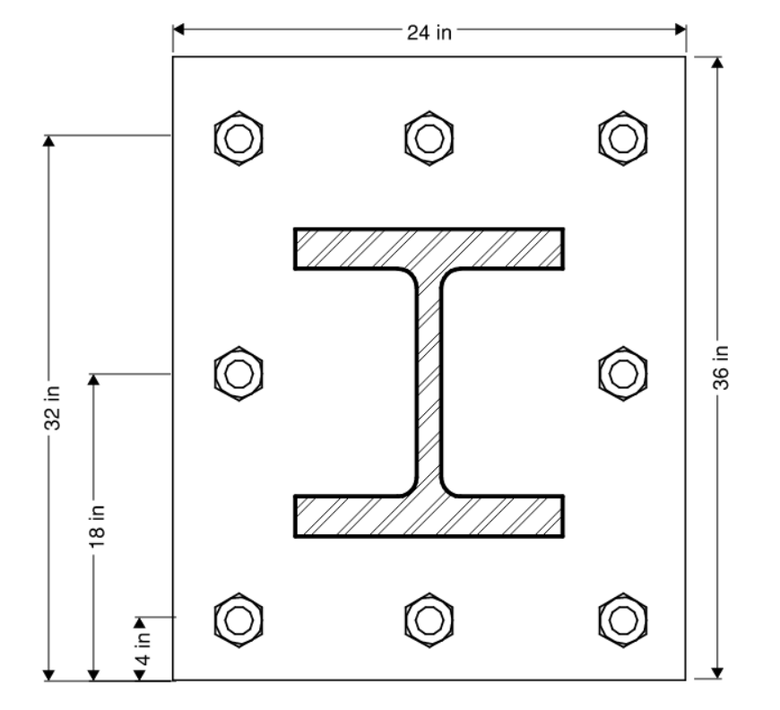 Figure 9: Base Plate Example
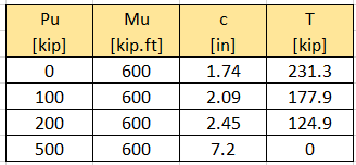
If we were to use the general methodology (see next section) that takes into account contribution from the middle row:

Ignoring the middle row of anchors is likely overly conservative. Furthermore, the fact that the closed-form solution above only works for compression + moment is a severe flaw.
4.4 Large Moment Base Plate (
We can generalize the closed-form solution above using the rigid plate assumption. Also known as “plane section remain plane” if you are dealing with section analysis. Either way, we are essentially assuming a linear strain profile.
Rather than conducting a full moment curvature analysis on a fiber section, the rigid plate methodology effectively turns this into a univariate root-finding problem.
- Assume rectangular bearing stress block with peak bearing stress (
- Assume rigid plate where anchor forces can be related linearly (i.e similar triangle)
Derivation
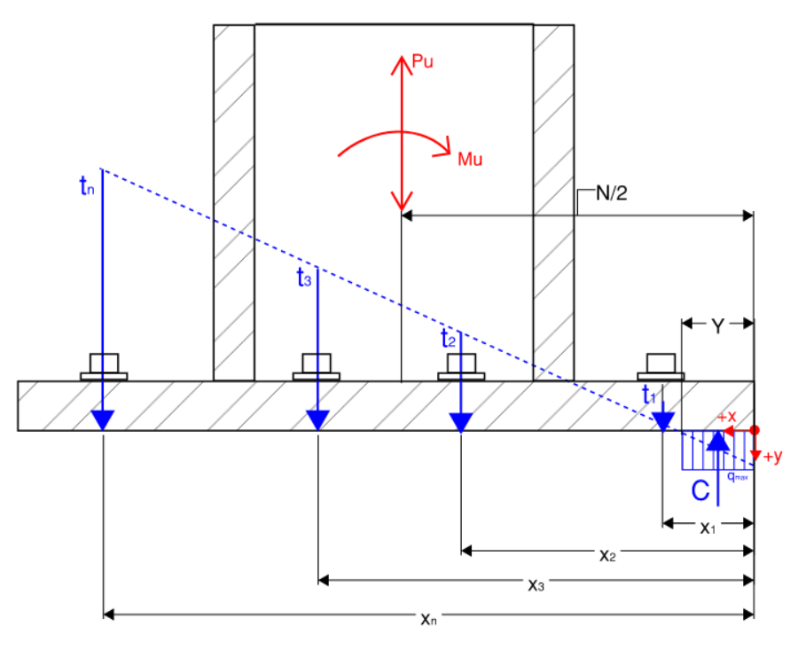 Figure 10: Free Body Diagram of Base Plate
Vertical force equilibrium:
Individual anchors can be related to each other using similar triangles:
Summation of anchor forces can be rewritten as:
Suppose we know the depth of neutral axis (
Once we know
The big question is how do we find the depth of neutral axis? The answer is to iteratively search for it using any root-finding algorithm. Or Solver in Excel.
For an assumed neutral axis depth (Y):
Compression bearing resultant: (equals to zero if Y is negative)
Anchor distance from neutral axis: (anchors within neutral axis depth are inactive and cannot take tension or compression, set to 0)
Anchor forces:
Total anchor row along each row:
Moment contribution of each row:
Force equilibrium is satisfied through our use of similar triangles to calculate
Moment equilibrium is only true if we have the correct neutral axis depth.
Keep trying different Y values until
Python Implementation
def rigid_plate_distribution(width, depth, fpc, Mu, Pu, x_i, N_i, beta = 0.80,
                             alpha = 0.85, alpha1 = 2.0, phi = 0.65):
    """
    Determine anchor rod uplift based on rigid base plate assumption.
    down = +ve, counter-clockwise = +ve
    Arguments:
        width = width of base plate (in)
        depth = depth of base plate (in)
        fpc = concrete strength (ksi)
        Mu = moment demand (kip.in). Always positive
        Pu = axial demand (kip). Positive is compression
        xi = depth of anchors from the edge [x1,x2,...]
        Ni = number of anchor along one row [N1,N2,...]
        beta (optional) = 0.80 (rectangular stress block parameter)
        alpha (optional) = 0.85 (rectangular stress block parameter)
        alpha1 (optional) = 2.0 (concrete bearing confinement factor)
        phi (optional) = 0.65 (concrete resistance factor)
    Return:
        T_i = list of total anchor force at each row []
        t_i = list of anchor force at each row [] = Ti / Ni
        Y_final = depth of neutral axis (in)
        sum_F = force equilibrium. Should always return 0
        sum_M = moment equilibrium. Should always return 0
    """
    # check eccentricity
    if Pu <= 0:
        e = None
        isSmall = False
    else:
        fpmax = phi * alpha * alpha1 * fpc
        qmax = fpmax * width
        e = Mu/Pu
        ecrit = depth/2 - Pu/2/qmax
        isSmall = (e < ecrit)

    # small eccentricity
    if isSmall:
        zeros = [0 for x in x_i]
        Y_final = depth - 2*e
        return zeros, zeros, Y_final, 0, 0

    # large eccentricity
    else:
        # secant method good for root finding
        def secant_method(func,x0=depth/2,x1=depth/2-1,TOL=0.1):
            while abs(func(x0)[0])>=TOL:
                x2 = x1 - func(x1)[0] * (x1 - x0) / (func(x1)[0] - func(x0)[0])
                x0 = x1
                x1 = x2
                print(f"Trial NA: {x0} \t {x1}")
            return x2

        # set up equation for root-finding
        def equilibrium_equations(Y):
            # Y could be negative. In which case no bearing.
            comp = min(0, -width*Y*phi*beta*alpha*alpha1*fpc)
            e_i = [max(0,x - Y) for x in x_i]
            omega_i = [a*b for a,b in zip(N_i,e_i)]
            if sum(omega_i) == 0:
                t_n=0
            else:
                t_n = (-Pu-comp) * (e_i[-1])/ sum(omega_i)
            t_i = [max(0, a/e_i[-1]*t_n) for a in e_i]
            T_i = [a * b for a,b in zip(t_i, N_i)]
            M_i = [a * b for a,b in zip(T_i, x_i)]
            sum_M = sum(M_i) + Pu*(depth/2) + comp*(Y/2) - Mu
            return sum_M, t_i, T_i, comp

        # start root-finding
        try:
            Y_final = secant_method(equilibrium_equations)
        except:
            raise RuntimeError("Did not converge")

        # final load distribution
        sum_M, t_i, T_i, comp = equilibrium_equations(Y_final)
        sum_F = sum(T_i) + Pu + comp

        return T_i, t_i, Y_final, sum_F, sum_M
User notes:
- Y can be negative. Indicates uplift without bearing (
- Stress profile for individual anchors (t) is linear which makes sense due to strain compatibility. Stress profile of entire row of anchor (T) does not have to be linear! Rows with more anchors (N) will have higher total force
- Keeping track of signs is a pain in the neck especially when moments get involved. I have a habit of auto-converting and losing consistency.
- Origin is at the right edge pivot point (see figure 10)
- left is +x, down is +y, by right-hand rule, counter-clockwise moment is positive (z axis is out of page)
- Therefore:
- C is always negative pointing up (or 0 if Y is negative)
- xi and ei should always be positive. Anchors within bearing region becomes inactive (set to 0)
- ti is always positive pointing down
- Mi is always positive because ti and xi are always positive
- Summation of moment and force should all be additions. Let the signs do the work.

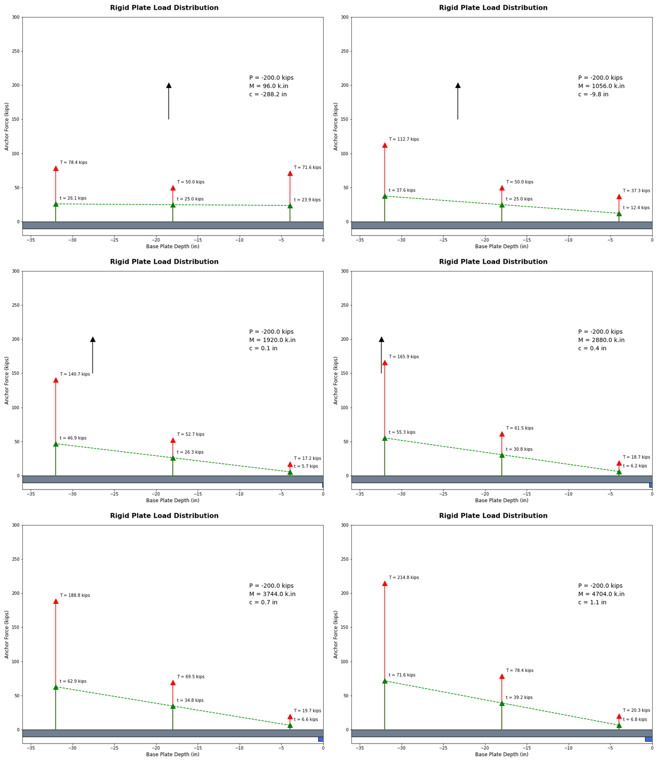 Figure 11: Example Base Plate with 200 Kips Tension
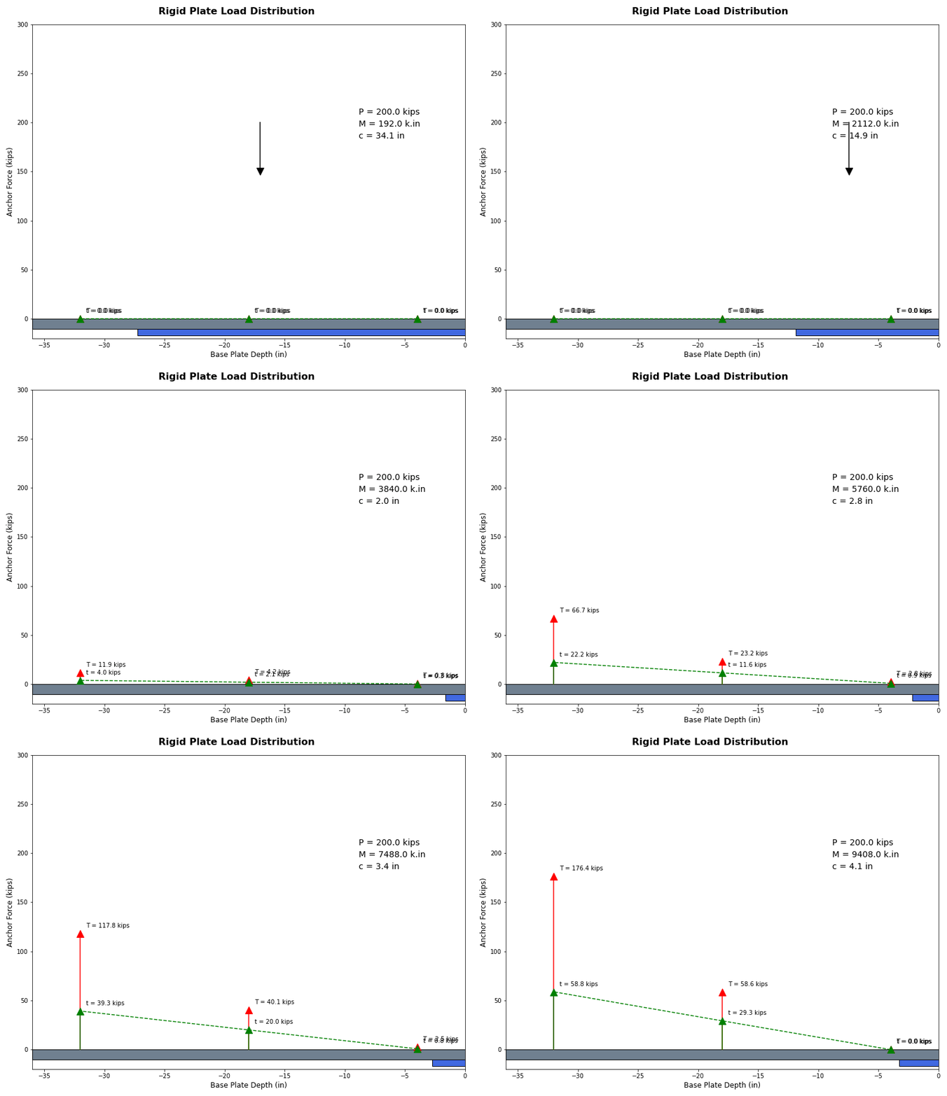 Figure 12: Example Base Plate with 200 Kips Compression
With all that derivation behind us, let’s clear up notations that you’ll see repeatedly:
- -
5.0 Failure Mode 1 - Concrete Bearing
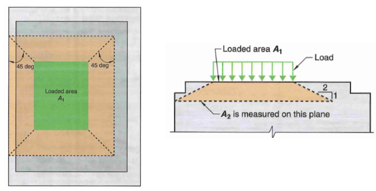 Figure 13: Concrete Bearing Confinement Factor
For large-moment base plates, Bearing DCR will always be 100% because contact with concrete is minimal and purely for equilibrium of a base plate on the verge of overturning. The contact area is equal to the neutral axis depth and bearing stress is equal to bearing capacity of concrete per our assumptions.
On the other hand, for small-moment base plates:
-
Determine confinement factor.
-
Calculate allowable bearing stress of concrete (resistance factor phi = 0.65):
-
Calculate bearing contact area. Recall contact length is reduced by presence of moment:
-
Bearing demand:
-
Bearing DCR:
Some notes:
- The bearing capacity equation provided in AISC 360 J8 and ACI 318 22.8 are equivalent.
- If your grout f’c is not 2x that of the concrete f’c, you may need to separately check bearing capacity of grout because grout is never confined (
6.0 Failure Mode 2 - Base Plate Bending
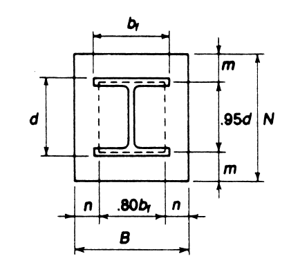 Figure 14: Base Plate Bending
Check to see if base plate is thick enough to withstand the design bearing stress. If not, our rigid plate assumption is invalid. The procedure is well-documented in AISC design guide but not codified. In essence, we are checking four yield mechanisms:
- Plate bending in major direction (cantilever extension along the depth direction)
- lever arm (m)
- Plate bending in minor direction (cantilever extension along the width direction)
- lever arm (n)
- Plate bending between web (based on yield line theory)
- lever arm (
- lever arm (
- Plate bending from anchor tension (if applicable)
- lever arm (xt)
The 0.8 and 0.95 coefficients you see in figure 14 are empirical. You may wish to adjust it as you see fit (if you’ve added stiffeners for instance). HSS columns would have 0.95bf instead of 0.8bf
-
Calculate bending lever arm in major and minor direction:
-
Calculate “lever arm” for bending between flange
-
Calculate moment demand due to bearing stress (fp) which we’ve determined from the previous section (unit is kip.in/in)
- If anchors are in tension, an additional tension plate bending mode should be evaluated. There is not really a codified way of doing this. The simplest method is to check one-way bending in the major direction
- AISC design guide 1 recommends calculating the lever arm (xt) from center of anchor rod to mid flange thickness.
- Refer to figure 7 for dimension “f”. The equation below are specific to what’s shown in fig 7. You may need to determine f and xt for your specific case (say if you want to calculate tension bending in minor direction, or some other yield line analysis)
- Note that we’ve divided the moment demand by base plate (B) width for consistent unit (kip.in/in) with the other modes of bending
-
Calculate plate bending DCRs (phi = 0.9. Using plastic section modulus):
-
Alternatively, the moment DCRs above can be expressed as a required thickness (as is the case in AISC design guide 1 which expresses required thickness as a function of bearing stress). A superior method is to express our thickness equation in terms of moment to allow for the tension case to be more easily incorporated.
- GR 36 or GR 50 base plates are readily available. You can get them as thick as 4”. Add stiffeners if you need more thickness. Adding stiffeners will significantly increase labor and complexity but is sometimes needed.
- I will not type out those elastic neutral axis, section modulus equations (too long…). Just search online. A stiffened section resembles a T-section
- Shape factor of a T-section is larger than 1.6! In other words, Stiffened base plate capacity is capped by 1.6Sx Per AISC 360-16 F11.1
Some other design notes:
- Note how lever arm n is inset more. Bending along two flange tip is more flexible than bending against an entire flange width
- The third bending mode (
- Some design software also checks a diagonal bending yield line at the corner of base plate
- The theory behind base plate bending between flange is described in the 1990 Thornton paper titled: “Design of Small Base Plates for Wide Flange Columns”. It’s only 3 pages long and very concisely written
- Base plate footprint should be as large as possible to reduce bearing stress (to the extent that the base plate is thick enough to prevent bending failure). In other words, try to keep your plate-bending DCR in all three directions to as close to 1.0 as possible for the most efficient base plate design.
7.0 Failure Mode 3 - Anchor Rod Tension
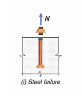
Anchor rod tension capacity can be calculated in two ways. Both will yield similar results. The AISC method is easier to apply as you do not need to calculate reduced diameter at threaded region.
- ACI 318-19 17.6.1.1
- uses a reduced area for threaded region but full strength
- AISC 360-16 J3.6
- uses a reduced strength but full cross-section area without considering threaded region
Three anchor rod grades commonly used.
- ASTM 1554 GR 36 (Fu = 58 ksi)
- ASTM 1554 GR 55 (Fu = 75 ksi)
- ASTM 1554 GR 105 (Fu = 125 ksi)
- Determine maximum tension demand for an individual anchor (t)
-
Check tension rupture capacity per AISC (phi = 0.75)
-
Check tension rupture capacity per ACI (phi = 0.75). See below for how to calculate
-
Use the minimum of the two:
-
Calculate anchor tension DCR
nt is the number of thread per inch. Thread geometry for unified coarse (UNC) can be found online. Example
 Figure 13: Effective Area of Threaded Rod
8.0 Failure Mode 4 - Anchor Rod Pullout
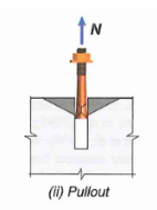
Pullout is calculated as the force at the onset of local concrete crushing at the bearing end of the anchor head. This is thought to be the beginning of a pullout failure because of the rapid decrease in stiffness afterwards. In other words, pullout capacity is purely a function of end bearing area, and is not related to embedment depth (i.e. friction neglected).
17.6.3.2.2 - For cast-in headed studs or bolts:
17.6.3.2.2 - For hooked ends anchors
17.10.5.4 - For seismic application, reduce pullout capacity by another 25% (phi = 0.7 for pullout)
There are two ways to get bearing area:
- Use area provided by the standard nuts (see table below for
- Provide a square washer plate at the bottom just for pullout (don’t forget to subtract area of rod itself)
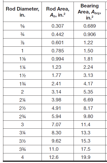 Figure 14: Bearing Area of Standard Nuts
9.0 Failure Mode 5 - Concrete Tension Breakout
This is arguably one of the more complex checks (along with shear breakout), which is why many software offload this check to HILTI PROFIS. We will only look at the most common breakout loading configurations.
Concrete breakout capacity will at most be around 300 kips. If you have much higher tension demand, it would make sense to skip all this complexity and go straight to anchor reinforcement, refer to the end of this section for some recommendations on that.
9.1 Concrete Breakout Capacity
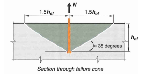 Figure 15: Concrete Tension Breakout Failure Cone
17.6.2.1b - For an anchor group:
That is a lot of variables. Let’s go through them one by one.
17.6.2.2 - Basic single anchor breakout capacity
This is the basic concrete breakout strength, of a single anchor, in cracked concrete. We will use this value as a starting point and apply several modification factors for other conditions.
where:
17.6.2.3 - Breakout Eccentricity Factor (
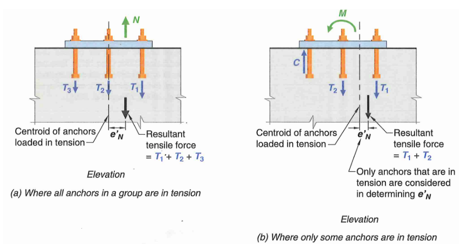 Figure 16: Anchor Tension Eccentricity Factors
If the resultant tension on an anchor group is concentric:
On the other hand, when a moment is applied to an anchor group, the resultant tension is not concentric meaning some anchors are more stressed in tension than others.
- For very large moments, the anchor closest to the neutral axis may need to be ignored when measuring
- For very large moments, the anchor closest to the neutral axis may need to be ignored when measuring

17.6.2.4 - Breakout Edge Effect Factor (
If the minimum edge distance is at least
Otherwise, if the anchor or anchor group is close to an edge:
17.6.2.1.2 - If there are 3 or more edges (less than
where “s” is the maximum spacing between anchors, and
17.6.2.5 - Breakout Cracking Factor (
Modification factor for cracking. Typically assume all concrete are cracked for conservatism unless more rigor is required. Cracked concrete has a modification factor of 1.0.
17.6.2.6 - Breakout Splitting Factor (
For cast-in anchors, or any anchors designed for cracked concrete, the splitting factor can be taken as 1.0.
17.6.2.1.4 - Full Projected Failure Area of Single Anchor (
Based on a 35 degree breakout cone, the projected failure area is a square with side length of
17.6.2.1.1 - Actual Projected Concrete Failure Area (
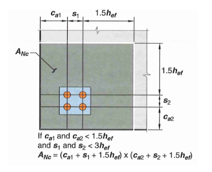 Figure 17: Concrete Breakout Area Example
For anchor group with 1 or 2 edges, the actual projected breakout cone area can be represented in equation form as:
However, the projected area must not exceed
For anchor group with 3 or more edges, effective embedment depth has to be reduced per 17.6.2.1.2. In essence, the breakout cone will extend
Putting Everything Together! (finally)
17.10.5.4 - For seismic application, reduce tension breakout capacity by 25%.
Note that the demand this time is the total tension force in the entire base plate assembly, not just a single anchor or a single row! Resistance factor (phi) for breakout is 0.7.
You’ll at most squeeze out about 300 kips capacity here. This is often not enough…
9.2 How to Add More Capacity
If you have incredibly high tension demand, you have two options. Don’t bother relying on concrete alone, it is not going to work.
- Extend anchor rods as deep as you can to widen the breakout cone, then add anchor reinforcements shown in blue below.
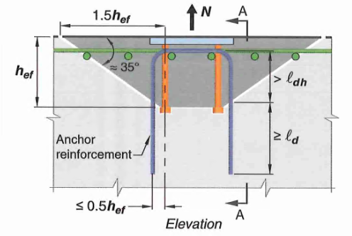 Figure 18: Anchor Reinforcement in Blue, Supplementary Reinforcement in Green
17.5.2.1 - Occasionally, it may be impossible to rely on concrete breakout capacity alone. In these cases, we may take breakout capacity as equal to the strength of all anchor reinforcements that can be developed on both ends of the splitting plane. Note we cannot rely on both concrete and steel together (i.e. do not add concrete and anchor steel capacity together)
- fy is the yield strength of anchor reinforcement
- As is the total steel area of anchor reinforcement
- use
There are stringent detailing requirements in order to take advantage of anchor reinforcements, here are some of the important ones:
- Reinforcement must be developed on both sides of the breakout line
- For tension breakout, anchor reinf. should be placed as close to the resultant tension as possible. No more than
- Available research data is based on #5 bars. Larger bend radii of larger bars may reduce effectiveness. Bar larger than #6 not recommended but not prohibited by code either.
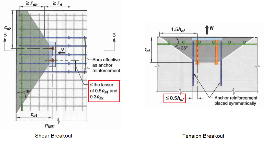 Figure 19: Effective Region for Anchor Reinforcement
DCR can be calculated as:
If that still doesn’t work…
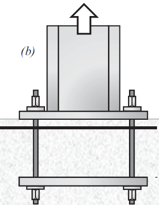
There is a hacky way to go about breakout checks that many practitioners use to circumvent Chapter 17 checks entirely.
- Extend it all the way through the footing like a through-bolt, then add a second embed plate at the bottom to induce punching shear rather than breakout.
This puts us outside the jurisdiction of ACI 318-19 chapter 17 into chapter 22. In fact, ACI 318-19 17.1.2 explicitly states:
“multiple anchors connected to a single steel plate at the embedded end of the anchors […] are not included in the provisions of this chapter [chapter 17]”
There are many advantages to checking punching shear instead of breakout:
- Compression demand is often higher than tension. So if it works for compression, uplift is okay by inspection!
- Punching shear capacity is often 2x to 3x higher than breakout
- Can add punching shear ties to drastically increase capacity
- Less detailing constraints
You might be asking at this point. What’s the difference? If we extend the anchors deep enough, doesn’t breakout BECOME punching shear? That’s a good observation. Refer to these two excellent paper for more information.
- “Tensile Strength of Embedded Anchor Groups: Tests and Strength Models” by Grilli and Kavinde.
- “Comparative Study of Punching Shear and Concrete Breakout” by Gaspar and Moehle. Actually by one of my colleague.
In summary:
- From the first paper:
- Chapter 17 equations were conservative (average test-prediction ratio of 1.34)
- Punching shear equations were unconservative! (average test-prediction ratio of 0.62)
- Paper cites depth-factor and effect of longitudinal reinforcement as primary contributor to the discrepancy
- From the second paper:
- Punching shear equation were based on mean predictor
- Breakout equations were based on 5 percent fractile (i.e. 95% of test data were greater than prediction)
- Can adjust between the two by applying a 0.75 factor and the new shear depth factor introduced in ACI 318-19
- Adjusting to same level of reliability resulted in similar capacities
Punching shear assumes a 45 degree failure plane; breakout assumes 35 degree. Ultimately this is all just semantics and we are looking at the same phenomenon! (just adjusted to different level of reliability).
10.0 Failure Mode 6 - Concrete Side Face Blowout
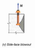
This check is commonly missed as it is tucked away in the recesses of ACI 318 chapter 17. This failure mode is only applicable for anchors near an edge (i.e.
17.6.4.1 - For a single headed anchor:
17.6.4.1.1 - if there is a second edge,
- In equation above,
17.6.4.2 - For head anchor group with anchor spacing along the edge
17.10.5.4 - For seismic application, reduce side face blowout capacity by 25%
As for demand, only consider tension in the anchors close to the edge (
11.0 Treatment of Shear Demand
The treatment of shear demand is a very interesting and nuanced topic. There are many detailing complications to consider! In a perfect world, shear check would be a straight forward 0.6FyAs. Unfortunately, the world is not perfect… To quote AISC design guide 1:
“It cannot be emphasized enough that the use of shear in the anchor rods requires attention in the design process to the construction issues associated with column bases.”
Option 1: Let anchor rod resist both tension and shear
Most important things to keep in mind:
- Because base plate anchor holes are so big, not all the anchors will be resisting shear uniformly. A common assumption is to assume only half of the anchors resist shear (e.g. say you have 6 anchors, assume only 3 are in contact with base plate)
- Alternatively, you may provide welded washers at every anchor to engage all anchors uniformly
- The anchors are not in pure shear. Some bending inevitably occurs (i.e. shear with lever arm). If you’ve provided welded washers, an additional check must be performed assuming bending within the base plate hole
- HCAI and DSA goes even further! The grout layer is treated like air for seismic applications. As a result, you end up having to check 3” to 6” of standoff distance, absolutely decimating your shear capacity (95% decrease…)
- A further 20% reduction in shear capacity is required per ACI 318-19 17.7.1.2.1 if you have a grout layer (no explanation given)
- AISC design guide 1 points to provisions in ACI 349-06 that allow for shear resistance through friction. This is not conservative and should be ignored in my opinion
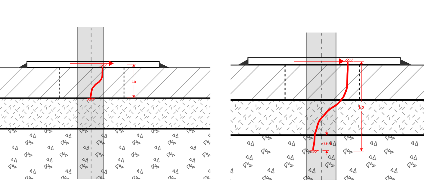 Figure 20: Through Thickness Bending For Base Plate Anchors
All things considered, I believe these are the viable options (listed from highest capacity to lowest):
- Option 1a: Assume only half of your anchors are in contact and won’t slip. Calculate shear capacity WITHOUT leverarm + 20% reduction per ACI to account for effect of grout
- Option 1b: Provide welded washers. All anchors are engaged. Calculate shear capacity WITH leverarm.
- lever arm measured from TOP of grout pad to mid washer thickness.
- Apply an additional 20% reduction per ACI to account for grout effect
- Option 1c: Provide welded washers. All anchors are engaged. Calculate shear capacity WITH leverarm.
- lever arm measured from BOTTOM of grout pad to mid washer thickness
HCAI and DSA may override ACI 318-19 17.7.1.2.1 and force you to check shear WITH leverarm (leaving you only option 1b or 1c)
Option 2: Provide shear lug or other bearing mechanism to decouple tension and shear
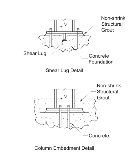 Figure 21: Resisting Shear Through Bearing
Shear lugs are becoming more popular especially with the addition of shear lug provisions in ACI 318-19. In the past, bearing mechanisms were provided in many different ways with varying design assumptions. The new provisions in ACI should bring some clarity and consistency in design.
Some of the common bearing methods include:
- Bearing by embedding base plate into footing.
- It should be said that this changes the load distribution drastically and its hard to say if our load distribution equations are still valid. Professor Kavinde at UC Davis has a few very insightful paper on design of embedded base plates.
- Bearing through grade beams.
- An additional level of structural beams are installed below grade and buried. The structural system effectively becomes a box and shear is transferred through studs in the grade beams
- Bearing through shear lug
Two codified methods for shear lug design are currently available. AISC design guide 1 recommends provisions within ACI 349-06 (for concrete design of nuclear structures) but the methodology is quite dated and somewhat unconservative. Instead, it is best to follow the latest provisions in ACI 318-19. (AISC design guide 1 will likely be updated soon to incorporate these ACI equations)
12.0 Option 1 - Base Plate Design With Shear Lugs
12.1 Introduction to Shear Lugs
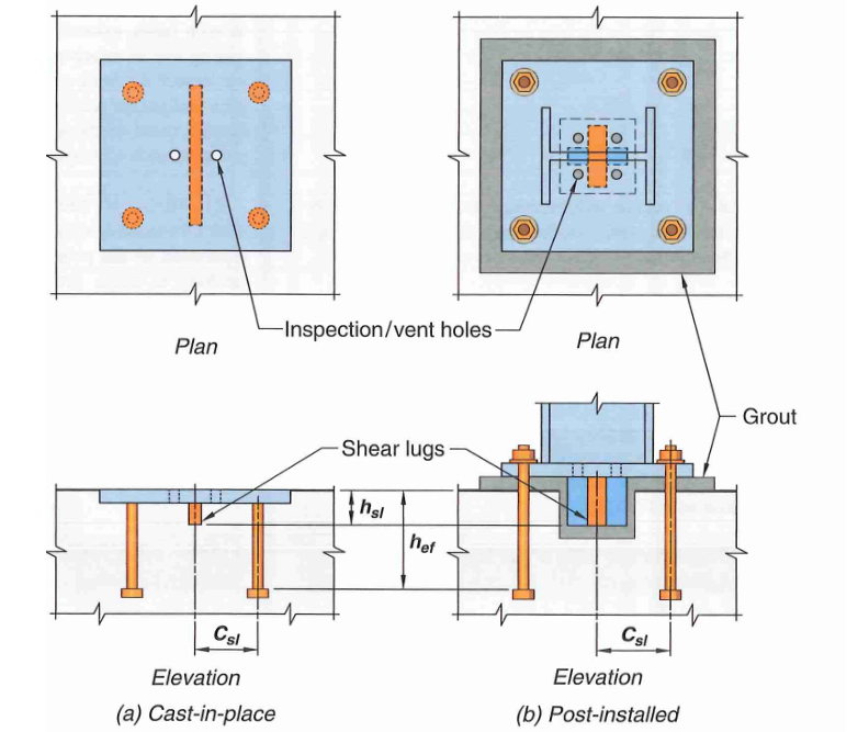 Figure 22: Shear Lugs
Shear lugs are rectangular plates, or steel shape composed of plate-like elements welded to a base plate. They resist shear via a bearing mechanism.
17.11.1.1.2 - Minimum of four anchor rods shall be provided when using a shear lug
17.11.1.1.3 - The use of shear lugs enable separation of shear and tension design, provided that the anchors are not welded to the base plate through washers. In AISC design guide 1, section 2.6 specifically states: “washers should not be welded to base plate, unless they are designed to resist shear”. If anchors are rigidly connected, displacement compatibility enforces a certain amount of shear into the anchor rods which must be accounted for. The applied shear that each anchor carries is calculated as shown:
- Anchor not welded or rigidly attached to base plate:
- Anchor welded to base plate (
17.11.1.1.8 - The following dimensional constraints must be satisfied in order to reduce interaction between breakout and anchor in tension.
- anchor embed depth to shear lug depth (
- anchor embed depth to distance between shear lug and centerline of anchor in tension (
17.11.1.1.9 - Moment due to shear lug shall be added to the overall design moment in the base plate. Luckily, it is purely a function of shear demand and your shear lug lever arm, so you won’t have to iterate your base plate design:
12.2 Failure Mode 7a - Shear Lug Bearing Capacity
17.11.2.1 - Bearing capacity of shear lug can be calculated as:
17.11.2.2 -
17.11.2.1.1 -
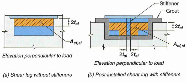 Figure 23: Shear Lug Bearing Area
Calculate shear lug bearing DCR (phi = 0.65):
12.3 Failure Mode 7b - Shear Lug Breakout Capacity
As was the case with tension breakout, shear breakout is long and complicated. A good alternative is to always provide enough shear anchor reinforcements.
It is also worth noting, if you are close enough to an edge, you need to check this limit state even if shear is parallel to the edge!
17.11.3.1 - Shear lug breakout capacity is calculated in the exact same way as regular shear breakout. The figure below summarizes the breakout area.
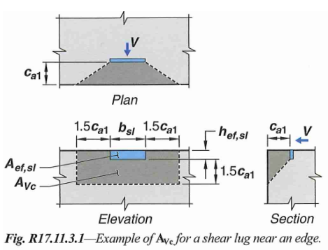 Figure 24: Shear Lug Shear Breakout Area
17.7.2.1b - For an anchor group:
17.7.2.1c - Note that shear breakout may also occur for shear acting parallel to an edge. The breakout capacity in these situations is determined by assuming load acting perpendicular to the edge, then multiply by 2. Edge factor should be taken as 1.
The equation above is essentially the same as tension breakout with a few subscript changes. Let’s go through them one by one.
17.7.2.2 - Basic single anchor shear breakout capacity
17.7.2.2.1 - This is the basic concrete breakout strength, of a single anchor, in cracked concrete. We will use this value as a starting point and apply several modification factors for other conditions. Use the ceiling value equation for shear lug.
17.7.2.3 - Shear Breakout Eccentricity Factor (
Assume shear is always concentric for shear lug design.
17.7.2.4 - Breakout Edge Effect Factor (
Shear breakout is always near an edge. What we are adjusting here is a second edge
If the
Otherwise:
17.7.2.5 - Breakout Cracking Factor (
Modification factor for cracking in shear breakout depends on rebar condition near the edge:
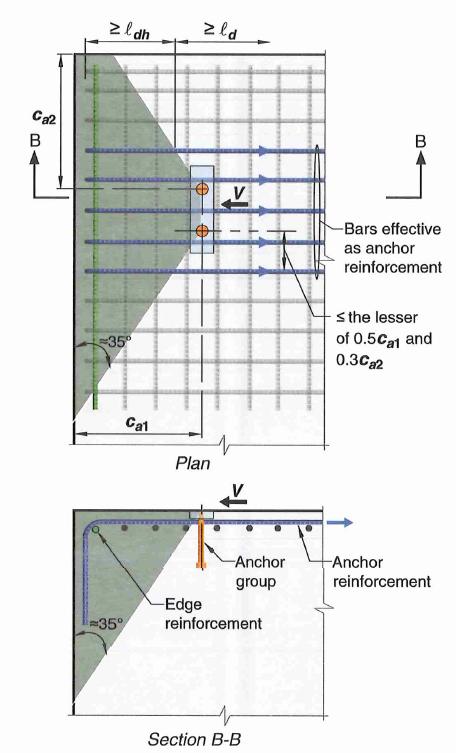 Figure 25: Shear Breakout Supplemental Reinforcement (in green)
17.7.2.6 - Member Thickness Factor (
Breakout capacity in shear is directly proportional to member thickness (
17.7.2.1.3 - Full Projected Failure Area of Single Anchor (
Based on a 35 degree breakout cone, the projected failure area is a rectangle with side length of
17.7.2.1.1 - Actual Projected Concrete Failure Area (
The actual breakout area must be adjusted depending on the perpendicular edge or anchor groups. However, the projected area must not exceed
- Essentially the breakout depth will be equal to
- The width of breakout extends
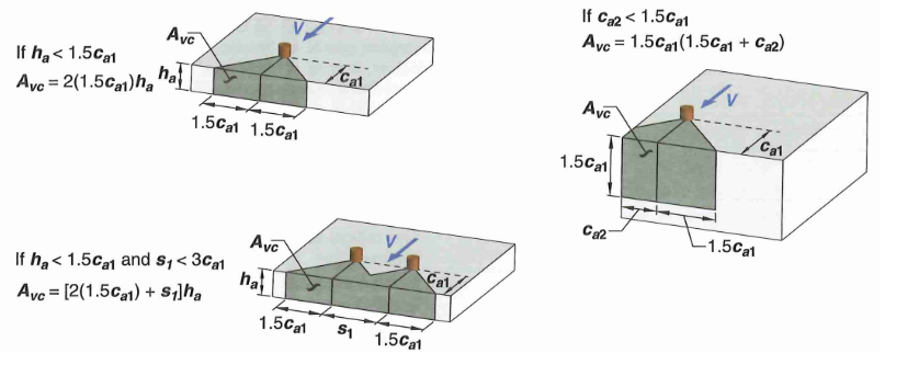 Figure 26: Concrete Breakout Area Example
17.7.2.1.2 - If the anchor is located in a narrow section where both its member thickness, and
- Larger edge distance:
- Member thickness:
Finally, the DCR can be calculated (phi = 0.7):
Again, if capacity from concrete alone is not enough, add anchor reinforcements:
- fy is the yield strength of anchor reinforcement
- As is the total steel area of anchor reinforcement
- use
12.3 Failure Mode 7c - Shear Lug Bending
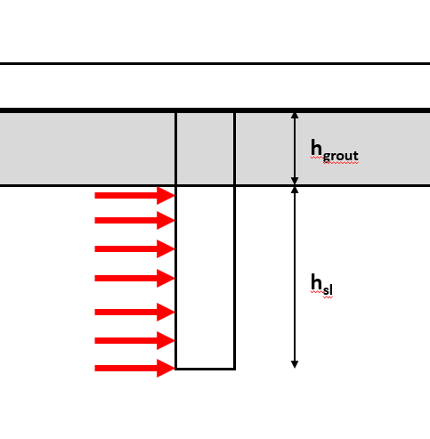 Figure 27: Shear Lug Bending
Lastly, shear lug must be thick enough to resist the bearing-induced bending. Remember to include thickness of grout layer in the cantilever!
Capacity calculated using plastic section modulus.
Shear lug bending DCR is calculated as shown. Note the shear lug can be CJP welded or fillet welded to the bottom. Weld design is outside the scope of this article.
Again, you may add stiffeners if you wish. The section properties can be calculated using any section property software or through equations online. Another option is to use a steel shape (such as an HSS section), but additional AISC checks would apply in those situations.
13.0 Option 2 - Base Plate Design Without Shear Lugs
13.1 Failure Mode 8a - Shear with Lever Arm (ETAG 001 Annex C 5.2.3.2)
ACI 318 chapter 17 is silent on shear with lever arm (commonly seen in cladding attachments). For more discussion on this subject, refer to the textbook “Anchorage in Concrete Construction” by Eligehausen, Malle, and Silva (2006). The research findings therein are codified in the European Organization for Technical Approval (ETAG 001 Annex C). This is the methodology used by HILTI PROFIS.
Rather than imposing additional normal stress due to flexure, the anchor bending capacity is converted to an equivalent shear capacity
Where:
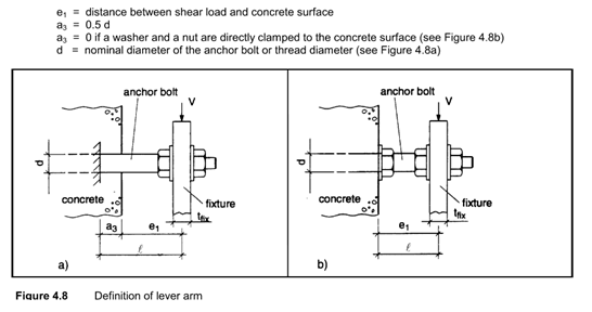 Figure 28: Lever Arm Distance
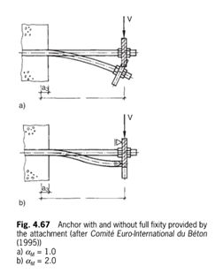 Figure 29: Single and Double Curvature
ETAG 001 Annex C treatment of Grout Layer
ACI does briefly mention the treatment of shear with grout pads. Per 17.7.1.2.1 the calculated steel shear strength must be reduced by 0.8 (regardless of thickness of grout). However, as we will see shortly, this is less conservative than the European equivalent standards by at least a factor of 3!
The conservatism from the European code primarily comes from the concern that thicker grout pads may spall, leading the front anchors transferring shear primarily via bending. Section 14.4.5.2.2 of the Eligehausen textbook provides the recommendation that lever arm may be neglected only if all the following conditions are satisfied:
- If grout thickness is less than
- If contact length of anchor to base plate is at least
- Not using oversized holes
For comparison purposes, a 1.5” diameter, GR 55 anchor rod, with 2” grout layer and 2” plate has the following nominal capacity in each code:
- ACI 318-19: 51 kips
- ETAG 001 Annex C: 16 kips (assuming tension DCR = 0)
- ETAG 001 Annex C: 10 kips (assuming tension DCR = 0.4)
Refer back to Section 11 for some nuances and options at your disposal. The DCR can be calculated as follows (phi = 0.65):
13.2 Failure Mode 8b - Shear Pryout
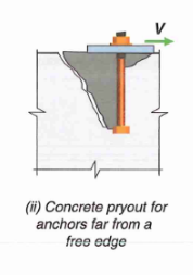
17.7.3 - Concrete pry out strength is simply calculated as a multiple of tension breakout strength (typically 2x).
For an anchor group:
Where:
DCR is calculated as follows (phi = 0.7):
13.3 Failure Mode 8c - Combined Tension and Shear Interaction
Shear and tension cannot be decoupled without bearing mechanisms as discussed in Section 11. We need to check the combined tension and shear interaction equations both in AISC and ACI.
- AISC 360-16 Commentary J3.7 - use rod tension rupture for tension DCR. Use rod shear with or without lever arm for shear DCR
- ACI 318-19 17.8.3 - use maximum of all chapter 17 tension/shear DCRs in the equation below
Appendix A - Base Rotational Spring Stiffness
There are two documents offering guidance on base connection spring stiffness:
- ASCE 41-17 Section 9.4.3.2.1 for partial-moment (PR) connections
- NIST GCR 17-917-45 “Recommended Modeling Parameters and Acceptance Criteria for Nonlinear Analysis in Support of Seismic Evaluation, Retrofit, and Design”
The ASCE 41 method offers a quick, low-fidelity estimate that may be good enough for some applications. The ATC method is much more nuanced and require very lengthy calculations of component deformations.
ASCE 41-17 Method
Assume a yield rotation of 0.003 to 0.005 rad (refer to code section for more information).
Calculate expected yield moment capacity assuming plate bending governs. You may need to use solver, or iteratively increase moment demand until base plate bending DCR = 1.0
The spring rotational stiffness is then calculated as:
NIST Nonlinear Modeling Guideline Chapter 4.5.8
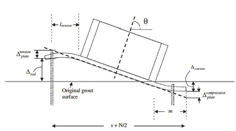 Figure A.1: Base Plate Component Deformations
Spring stiffness can be calculated as yield moment divide by yield rotation.
Yield moment is equal to the minimum design moment based on limit state of a.) plate bending (bearing side) b.) plate bending (tension side) c.) tension rupture of anchor rods. Similar to the ASCE 41 method above, you might need to iteratively increase moment demand until one of the DCRs reach 1.0.
Now calculate the individual component deformations which include a.) axial lengthening of anchor rods, b.) bending deformation of base plate, and c.) compression shortening of concrete
The deformations can be converted to an effective rotation:
A couple of notes:
- From my experience, anchor rod extension seems to be the biggest contributor. However, this is based entirely on your assumption of stretch length (
- Concrete deformation is a close second
- Plate bending deformation is always the smallest. Essentially negligible for base plate with stiffeners.
- Amount of axial load (Pu) affects yield moment significantly. Higher axial load = stiffer
0 Comments