Primer: ASCE 7-16 Seismic Chapters.
“Primers” are my personal notes on various technical topics in structural engineering. Building codes are dense and voluminous, sometimes written in legalese rather than in sentences that can be easily understood. I write these “Primer” so I can gather, organize, and condense technical topics I encounter as an engineer. Please understand I made these for myself. Reader discretion is advised. No warranty is expressed or implied by me on the validity of the information presented herein.
- 1.0 Basic Earthquake Concepts
- 2.0 Earthquake Organizations, Codes, and Standards
- 3.0 General Seismic Provisions
- 4.0 Seismic Provisions for Building Structures
- 4.1 Seismic Force Resisting System (SFRS)
- 4.2 Combination of Systems
- 4.3 Building Irregularities
- 4.4 Procedure Selection and Modeling
- 4.5 Equivalent Lateral Force Procedure (ELF)
- 4.6 Period Determination
- 4.7 Story Drifts, and Separations
- 4.8 P-Delta, Stability, Orthogonal Effects, and Other Considerations
- 4.9 Seismic Load Effect and Combinations
- 4.10 Simplified Procedure
- 5.0 Seismic Provisions for Nonstructural Components
- 6.0 Seismic Provisions for Nonbuilding Structures
- 7.0 Diaphragm and Walls
- 8.0 Wood Diaphragms and Shear Walls
- 9.0 Miscellaneous. Inspections. Professional Engineers Act. Etc.
- Appendix: Helpful Tables and Other Stuff
1.0 Basic Earthquake Concepts
1.1 Basics
- Hypocenter (focus) - the place in Earth’s crust where energy is released (below ground)
- Epicenter - the point on Earth’s surface directly above hypocenter
- Focal depth - the depth from surface to hypocenter
- Epicentral distance - distance between epicenter and the observing station
- Foreshocks - smaller shocks before the major event. Occurs occasionally
- Aftershocks - smaller shocks after the major event. Always occurs with diminishing intensity
- Fault creep - slow continuous movement which is not noticeable.
- Surface rupture - when movement of fault breaks through to the surface
- Dip angle - angle of incline of the fault plane
1.2 Earthquake Faults
- Fault - fracture in Earth’s crust (edge of tectonic plate)
- Vertical fault movement - dip-slip fault
- Normal fault - Hanging wall moves down, exposing slope downwards
- Reverse fault - Hanging wall pushes up, creating a cliff
- Horizontal fault movement - strike-slip fault
- Left/Right lateral fault
- Both vertical and horizontal movement - oblique-slip fault
- Most faults in California are near vertical breaks with predominantly horizontal movement. San Andreas Fault is right-lateral fault more than 600 miles long
- Seismic sea wave (Tsunami) - occur due to vertical fault movements. Strike slip faults do not create tsunami
1.3 Seismic Waves
- P-waves, Primary waves, compression waves - Fastest to arrive. Similar to sound, compresses and expand earth material. Both horizontal and vertical component
- S-waves, Secondary waves, shear waves - slower than p-wave, responsible for most of the damage near epicenter. Significant horizontal and vertical shaking
- Surface waves, Love waves, Rayleigh waves - like long rolling ocean waves. They are the slowest and only occurs near the surface. Slow to damp out. Responsible for greatest damage far from epicenter
- PGA - peak ground acceleration. Maximum value recorded in acceleration record. A spike.
- EPGA - effective peak ground acceleration. Buildings don’t often respond to sudden spikes of PGA. EPGA is theoretically the max ground acceleration to which a building responds to.
1.4 Earthquake Strength and Intensity
-
Magnitude (M) - Richter Scale - measures earthquake’s size. Magnitude (M). Richter scale is logarithmic. Each single digit increase in magnitude, shaking goes up by a factor of 10. Good for quantifying length of fault rupture, duration, and total energy release
-
Energy Release (E) - the energy radiated can be approximated with the following equation by Gutenberg and Richter. Each single value increase in magnitude represents 32-fold increase in amount of energy released
- Intensity (I) - A measurement based on the amount of observed damage and is subject to human interpretation. Does not depend on measurements! Thus can assign intensity to past earthquakes. Intensity decreases the further you are from epicenter (unless significant soil amplification is present). Modified Mercalli Intensity Scale (MMI) ranges from I to X
- I = no damage nor shaking
- V = moderate shaking, very light damage
- X+ = extreme damage and shaking
- Refer to page 8 of SDR workbook for full table
Longer fault rupture -> longer duration -> larger magnitude -> higher intensity
- Attenuation is the decrease in seismic energy received with increasing distance from epicenter. The attenuation effect is due to viscous properties of rocks and soil, scattering, and etc.
- Shorter period P-waves and S-waves attenuate (energy decreases) much faster
1.5 Basics of Structural Dynamics
Stiffness of frame members. Remember to convert span to inches for consistent unit
\[k_{fix-fix} = \frac{12EI}{L^3}\] \[k_{fix-pin} = \frac{3EI}{L^3}\]For several frame members along a resistance line, the floor displacement can be assumed equal along its length. Thus the configuration becomes spring in series:
\[F_i = F_{total} \frac{k_i}{\sum k_i}\]Since we know the force taken by the column, the column shear is constant, and the moment can be calculated as:
\[M = \left\{ \begin{array}\\ Vh/2 & \mbox{if } \ \mbox{double curvature} \\ Vh & \mbox{if } \ \mbox{single curvature} \end{array} \right.\]Dynamic Properties:
- Angular frequency (rad/s)
- Natural frequency (Hz)
- Natural period (s)
- Gravity constant
- The first mode is the fundamental mode and has longest period. Subsequent higher modes have shorter period (approximately divide by 3 each mode up). Behavior of typical buildings dominated by first-mode
1.6 Damping
- Damping slowly brings an oscillating system to a stop. The critical damping ratio is the precise amount of damping such that the oscillation stops the quickest.
- Buildings usually have damping no where near the critical damping (usually 2% to 5% of that)
- Period of vibration actually increases with larger damping. however for most building structures, due to small damping:
1.7 Earthquake Spectra
- Obtaining the entire response history of a SDOF system due to a specific ground motion record:
- spectral acceleration (\(S_a\)) is the peak acceleration
- spectral velocity (\(S_v\)) is the peak velocity
- spectral displacement (\(S_d\)) is the peak displacement
- For a single ground motion record, if we record the spectral acceleration for varying period of vibration (i.e. T on the x-axis, Sa on the y-axis), we obtain our response spectrum
- Response spectra is a collection of response spectrum with varying damping ratio (\(\beta\)) and soil type (S)
- increasing damping ratio (\(\beta\)) flattens the spectrum curve
- soil type (S) affects the shape of spectrum curve. Stiffer soil have peak at shorter period, softer soil have peak into the long period range
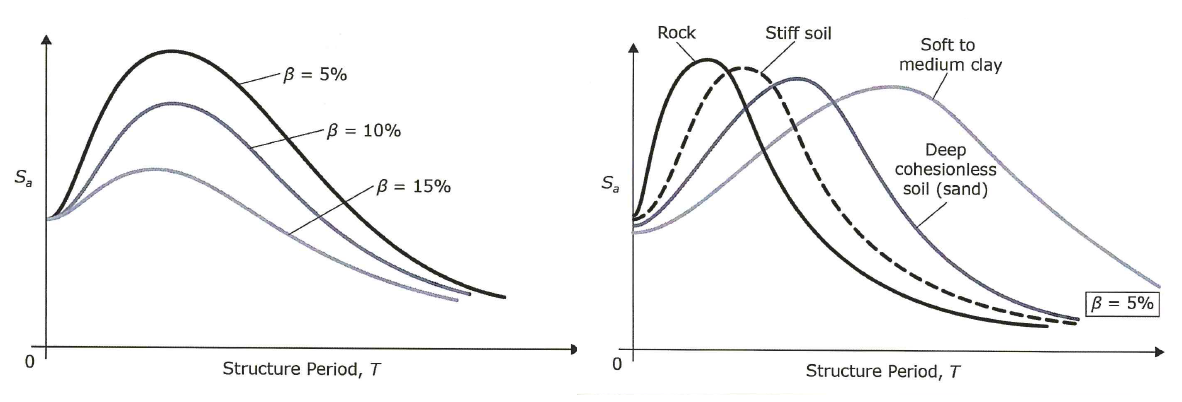 Figure 1: Earthquake Spectra
- Resonance occurs when the structure’s natural period is similar to the predominant earthquake period or the soil period. Structures have tendency to yield and as damage accumulates, its period also lengthens
- Base shear can be calculated using an earthquake spectra (exactly for SDOF, approximate for MDOF)
- If Sa is given as a %g, simply multiply by the weight (W)
2.0 Earthquake Organizations, Codes, and Standards
2.1 Organizations
- NEHRP - National Earthquake Hazards Reduction Program
- Established in 1977 with goal of reducing risk of damage to life and property from earthquakes
- Works in close coordination with other agencies like NIST, FEMA, NSF, USGS to develops design and construction practices and guidelines which may be adopted in future building codes
- ASCE - American Society of Civil Engineers
- Oldest national professional engineering society. Seeks to promote the Civil Engineering profession
- SEI - Structural Engineering Institute is a sub-division that is more concerned with structural engineering. They lead the effort in development of ASCE 7
- ICC - International Code Council
- Established in 1994 as a non-profit organization
- Develops the International Building Code, which is in turn adopted by local state jurisdictions
- SEAOC - Structural Engineers Association of California
- An association of engineers in California. It’s mission is to advance the profession, provide continuing education, public outreach, and so forth
- ATC - Applied Technology Council
- Established in 1973 through the efforts of SEOAC
- Goal is to develop sate of the art, user-friendly engineering resources
- e.g. ATC-7 is guidelines for wood diaphragms, ATC-20 is procedure for post-earthquake evaluation
2.2 Building Code and Standards
- FEMA 450-2003: primary resource which is used by ASCE 7-05, IBC 2006 and 2009
- FEMA P-750-2009: primary resource which is used by ASCE 7-10, IBC 2012 and 2015
- ASCE 7: Used to determine minimum design loads to be applied on structures
- IBC: International Building Code. A model building code that provides the minimum regulation for building systems
- For single family homes, townhouses less than or equal to 3 stories, these structures are simple and can follow the more prescriptive IRC
- IRC: International Residential Code. Stand-alone code that has prescriptive provisions for single family dwellings and townhouses.
- CCR: California Code of Regulations has 28 parts. Title 24 is specifically for building standards and has 12 parts:
- CAC = California Building Standards Administrative Code = administrative regulations
- CBC = California Building Code, based on IBC
- CRC = California Residential Code, based on IRC
- CEC = California Electrical Code
- CMC = California Mechanical Code
- CPC = California Plumbing Code
- California Energy Code for energy conservation
- No longer used
- CHBC = California Historical Building Code
- CFC = California Fire Code
- CEBC = California Existing Building Code
- Despite its name, this code only covers existing URM bearing wall buildings
- California Green Building Standards Code
- California Reference Standards Code
- SEAOC Blue Book was last printed in 1999 and summarizes the recommendations of earthquake construction at the time. Engineers now should seek the commentaries of ASCE 7-16 for similar contents
- Performance-Based Seismic Design (PBSD) is a new development that categorizes a building’s seismic performance to different categories which aids the owner in decision making. SEAOC Vision 2000 was the impetus for this project
- ASCE 41: Seismic Evaluation and Retrofit of Existing Buildings is the current standard for PBSD and is a combination of multiple decades of research. It is used mainly for existing buildings but can be used for new building via CBC clause 104.11 subject to building official approval. There are five performance levels:
- S-1: Immediate Occupancy
- S-2: Damage Control
- S-3: Life Safety
- S-4: Limited Safety
- S-5: Collapse Prevention
- To map this to ASCE 7-16:
- MCE = maximum considered event = 2500 yr return period
- DBE = design event = 2/3 MCE
- frequent event = return period of around 100 years
- For risk category II (Ie = 1.0):
- Collapse prevention for MCE
- Life safety for DCE
- Immediate occupancy for frequent
- For risk category IV (Ie = 1.5):
- Life safety for MCE
- Immediate occupancy for DCE
- Operational for frequent
3.0 General Seismic Provisions
This chapter is mostly a summary of ASCE 7 section 11 which is a guideline for constructing an earthquake spectrum for seismic design.
3.1 General Requirements of IBC
- The purpose of the IBC is to establish a set of minimum requirements. Afterwards, each jurisdiction adopt the IBC and add their own specific set of requirements. IBC derives heavily from codes and standards such as ASCE 7 and often makes reference to them. Should any differences occur, the IBC provisions should govern.
- IBC 1603.1.5 - The following seismic design data should be made available on the construction document. This chapter will provide guidance on how to obtain the first 6, and chapter 4 will be on the rest.
- Risk category
- Importance factor
- Mapped spectral response acceleration parameters
- Site class
- Design spectural response acceleration parameters
- Seismic Design Category
- Type of Seismic Force Resisting System (SFRS)
- Design base shear (V)
- Seismic response coefficient (Cs)
- Response modification coefficient (R)
- Analysis procedure used
- IBC 1604.10 - Seismic detailing requirements must be met even if wind demand is higher. This is because seismic demand is inherently unpredictable and structures are design to response inelastically
- IBC 1613.1 - The following structures are exempt from the requirements of IBC and ASCE 7:
- One to Two family dwellings (detached residental housing) with low seismicity (SDC = A, B, or C or Ss < 0.4)
- Simple wood-frame buildings with very prescriptive design per IBC 2308 or CRC
- Not very important storage structures only for incidental human occupancy
- Special structures that are not explicitly addressed and have other regulations providing seismic criteria: such as bridges, transmition towers, dams, nuclear reactors, etc.
3.2 Risk Categories
- Every building is assigned one of four risk categories. Refer to IBC 1604.5 for full list. Refer to ASCE 7-16 Table 1.5.2 for importance factors. Where a building contains two or more occupancy, the more critical governs.
| Risk Categories | Examples | Importance Factor |
|---|---|---|
| I | Low importance - barns, temporary facilities, minor storage facilities, and etc. | 1.0 |
| II | Typical importance - majority of buildings will fall within this category, offices, residential buildings, and etc. | 1.0 |
| III | High Importance - buildings with high occupancy such as high-rises downtown, jail, public assembly hall, power station and water treatment not included in risk category IV. Buildings containing sufficient quantities of toxic materials | 1.25 |
| IV | Essential - facilities that must be operational after an emergency. Hospitals, police stations, emergency shelters, communication centers, emergency power stations, aviation control tower, buildings critical to national defense, water storage facilities required for fire suppression | 1.5 |
- Risk category will be used to determine the following later:
- importance factor
- seismic design category
- spectral response parameters
- allowable story drift
- response coefficient (Cs) and base shear (V)
- structural observation requirements and many others
3.3 Ground Motion Parameters
The first step in constructing the design spectrum is to obtain the “Mapped MCER Acceleration Parameters” (\(S_S ~ \mbox{and} ~ S_1\)). The values can be read from IBC Figure 1613.3.1(1) to Figure 1613.3.1(1), or figures in ASCE 7-16 chapter 22. More commonly, the are obtained through online tools such as this one: https://seismicmaps.org/
- These two parameters are based on the “Risk-Targeted Maximum Considered Earthquake” (MCER); which is the most severe ground motion currently considered in design (1% probability of collapse in 50 years, or a 5000 year return period)
- The design earthquake ground motion is 2/3 of MCER. Buildings designed to this level should have a collapse probability of nor more than 10% if the MCER event were to occur
3.4 Site Classification
Another important parameter to determine before we can construct our design spectrum is the site soil properties; which is classified from A to F. It is typically determined through shear wave velocity measurements and standard penetration tests.
- A - Hard Rock (very rare in California)
- B - Rock
- C - Very dense soil
- D - Stiff soil (default if no geotechnical information is available)
- E - Soft clay soil
- F - special circumstance that require site-specific evaluation
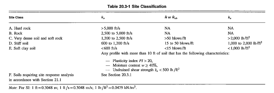 Figure 2: Site Soil Classification (section 20 of ASCE 7-16)
These site classifications will be used to determine ground motion amplification. Softer soil tend to amplify seismic force more than stiffer soils.
3.5 The Design Response Spectrum
- Collect site information, soil class, risk category, and ground motion parameters (\(S_S ~ \mbox{and} ~ S_1 ~ \mbox{and} ~ T_L\))
-
Determine the necessary site adjustment factors (\(F_a ~ \mbox{and} ~ F_v\)) from IBC 1613.2.3 which is more updated than ASCE 7-16
 Figure 3: Short Period Site Coefficient Fa
\[F_{interpolate} = F_{low} \pm \frac{F_{high} - F_{low}}{S_{high} - S_{low}} \times (S_{int} - S_{low})\]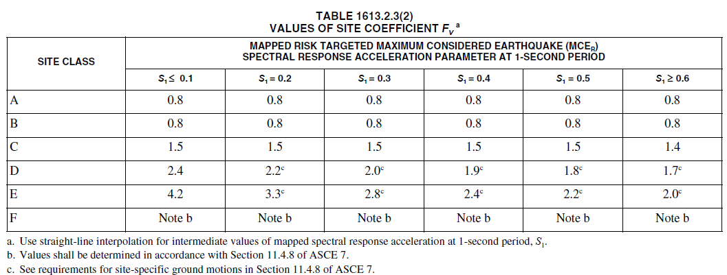 Figure 4: Long Period Site Coefficient Fv
 -
Determine the site-adjusted MCER spectral acceleration parameters (ASCE 7-16 11.4.4)
\[S_{MS} = F_a S_S\] \[S_{M1} = F_v S_1\]- If a site investigation per ASCE 7-16 chapter 20 was performed to validate rock condition (class B), but no shear wave velocity was taken, then take both adjustment parameter as unity (1.0)
- If geotechnical investigation is not available and the default site class D is selected, \(F_a\) cannot be lower than 1.2 regardless of response parameters
- Refer to site-specific ground motion procedures of ASCE 7-16 11.4.8 to see if additional requirements apply
- Need to conduct site specific analysis per ASCE 7-16 section 20.3.1 for any class F sites
- Need to conduct site specific analysis per ASCE 7-16 section 20.3.2 for the following:
- seismically isolated, or specially damped structure with S1 > 0.6
- class E structures with Ss > 1.0
- CAN AVOID IF: T < Ts and using equivalent static force procedure
- class D and E structures with S1 > 0.2
- CAN AVOID IF: Cs is taken as the plateau value from 0<T<1.5Ts, and amplified Cs value by 1.5 for 1.5Ts < T < TL
-
Calculate the Design Spectral Acceleration Parameter which is 2/3 of the site-adjusted value above. Note that the spectral assumes by default a 5% damping ratio (ASCE 7-16 11.4.5)
\[S_{DS} = (2/3) S_{MS}\] \[S_{D1} = (2/3) S_{M1}\] - To summarize all the variables so far:
- velocity domain \(S_1 \rightarrow F_v \rightarrow S_{M1} \rightarrow S_{D1}\)
- acceleration domain (plateau) \(S_s \rightarrow F_a \rightarrow S_{MS} \rightarrow S_{DS}\)
-
Construct the design spectrum
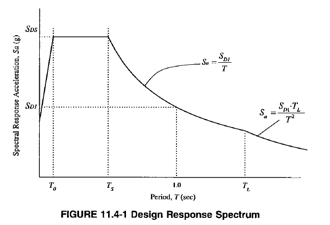 Figure 5: Design Response Spectrum
- Note there are 4 distinct regions on the spectrum plot divided by four important periods (ASCE 7-16 11.4.6)
-
Linear ascending region at very short period range. For static force procedure, this stage is neglected and instead the plateau value is used
\[S_a = S_{DS}(0.4 + 0.6(T/T_0))\] -
The plateau region
\[S_a = S_{DS}\] -
The tail region for moderately long period structure
\[S_a = \frac{S_{D1}}{T}\] -
The region for extremely long period structures (extremely rare)
\[S_a = \frac{S_{D1}T_L}{T^2}\]
3.6 Seismic Design Category (SDC) - ASCE 7-16 11.6
Seismic design category (SDC) ranges from A to F:
- A = very low hazard
- B = low hazard
- C = moderate
- D = moderate to high
- E = high hazard
- F = high hazard + essential facility
Seismic design category is used to determine the following:
- Building height restriction
- Permitted analysis procedure
- Permitted lateral force resisting system
- Permitted irregularities
- SFRS detailing implications
- Non-structural anchorage implication
SDC can be determined using the procedure below:
- If \(S_1 \geq 0.75\), and risk category I, II, or II => SDC = E
- If \(S_1 \geq 0.75\), and risk category IV => SDC = F
-
Otherwise, SDC is determined based on \(S_{DS}\) and \(S_{D1}\) values and the tables below (ASCE 7-16 Table 11.6-1,2). The more severe category governs.
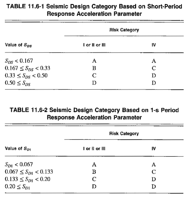 Figure 6: Seismic Design Category Determination
 - In some cases, we can use only the \(S_{DS}\) values to determine SDC provided the following conditions are satisfied:
- approximate period of structure (Ta) is less than \(0.8T_s\) (well within plateau region)
- period used to calculate drift is less than \(T_S\)
- seismic response coefficient determined as the plateau value (\(\frac{S_{DS}}{R/I_e}\))
- diaphragm is rigid. If not rigid, diaphragm cannot span more than 40 ft
ASCE 7-16 11.7: For structures assigned to SDC A (pretty much never in California), the seismic hazard is low enough such that lateral force can be determined through ASCE 7-16 1.4 for general integrity (also must design for wind)
- Base Shear
- Vertical Distribution of Lateral Force (similar for diaphragm force)
- Non-structural anchorage to main structure
- Wall anchorage force
4.0 Seismic Provisions for Building Structures
The following is a summary of key provisions in ASCE 7-16 chapter 12 which is related to design of building structures.
4.1 Seismic Force Resisting System (SFRS)
- Horizontal system = diaphragm and any horizontal trusses
- Vertical system = the lateral system (e.g. shear wall, braced frame, moment frame, etc)
ASCE 7-16 Table 12.2-1 is a giant table that contains the design coefficients (\(R,\Omega_o,C_d\)) and height limitation depending on the building’s SDC. Here are some of the most common values:
| Seismic Force Resisting System | \(R\) | \(\Omega_o\) | \(C_d\) |
|---|---|---|---|
| Special reinforced concrete shear wall | 5, 6* | 2.5, 2.5* | 5, 5* |
| Special reinforced masonry shear wall | 5, 5.5* | 2.5, 2.5* | 3.5, 4* |
| Ordinary reinforced concrete shear wall | 4, 5* | 2.5, 2.5* | 4, 4.5* |
| Ordinary reinforced masonry shear wall | 2, 2* | 2.5, 2.5* | 1.75, 2* |
| Light-frame wood with WSP sheathing | 6.5, 7* | 3, 2.5* | 4, 4.5* |
| Special concentric braced frame | 6 | 2 | 5 |
| Ordinary concentric braced frame | 3.25 | 2 | 3.25 |
| Eccentric braced frame | 8 | 2 | 4 |
| Special steel moment frame | 8 | 3 | 5.5 |
| Ordinary steel moment frame | 3.5 | 3 | 3 |
| Buckling-restrained braces | 8 | 2.5 | 5 |
Note: Values with asterisk (*) relates to building frame system (non-bearing). In other words, not resisting significant amount of vertical gravity load, only purpose is resisting seismic lateral load
Definition of types of systems:
- Bearing Wall System: seismic element such as a shear wall that ALSO SUPPORTS significant vertical gravity load
- Building Frame System: seismic element that is mainly for lateral load. DOES NOT SUPPORT significant vertical gravity load (NOTE that many SFRS appear in BOTH categories. Need to ensure we are picking the correct one)
- Moment Frames
- Dual system: two or more types of SFRS IN THE SAME DIRECTION. Having shear wall in EW direction, and moment frame in NS direction is NOT a dual system
- Other less common systems like cantilever column, wall infill, etc
What do these seismic factors mean?
- \(R\) - is a measure of inherent overstrength and ductility. Higher R = more ductility
- \(\Omega_o\) - factor to amplify demands to represent the maximum possible inelastic force developed during design based earthquake
- \(C_d\) - is a displacement amplification factor
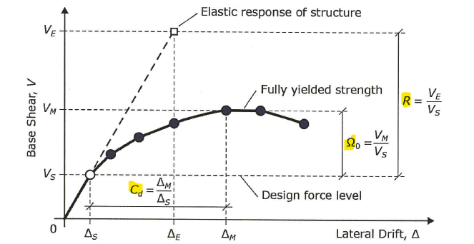 Figure 7: Seismic Factors Meaning
The logic is as follows:
- Almost all conventional design software uses elastic, first-order analysis. However, designing a buildings to withstand earthquakes without yielding is cost-prohibitive, and often not possible
- In addition, buildings have capacity to absorb damage through deformation (ductility). As building becomes damaged, the period lengthens and damping increases, both allows the building to attracts less acceleration
- For most buildings, the goal is to prevent collapse, not ensuring zero damage. Therefore perhaps we can design for a smaller demand, in essence hoping ductility will take care of the rest
- Divide actual response by R to reduce the design force. And design using first-order elastic analysis despite the actual response being far into the inelastic region
- For elements that must remain elastic, multiply demand by \(\Omega_o\)
- Dividing base shear by R also reduces displacement as shown in the figure above. However, inelasticity inherently means more displacement. In order to ensure we don’t underestimate displacement, multiply predicted value by Cd
The table also lists permitted height of the building where NP = Not Permitted, NL = Not Limited. Alternatively, specific values are provided between 60 ft to 240 ft. Special considerations can be taken to increase the height as described in these provisions:
- ASCE 7-16 12.2.5.4 For EBF, SCBF, BRB, steel special plate shear wall, special concrete shear wall
- ASCE 7-16 12.2.5.6 for steel OMF
- ASCE 7-16 12.2.5.7 for steel IMF
Remember to not include parapet height into the overall building height.
4.2 Combination of Systems
- Combination of System In Different Direction: Use the respective coefficients for each system in the two orthogonal directions
- Combination of System In The Same Direction: Considered dual system. Refer to Table 12.2-1 for valid coefficient to use. If not listed, use the more stringent R value and the corresponding \(C_d\) and \(\Omega_o\) factors
- Combination of System Along Height of Building: Example: moment frame in the superstructure transitions to basement shear wall at the bottom.
- If upper system has lower response modification (less ductile), use it for both
- If upper system has higher response modification (more ductile), use the respective coefficients for each system. However, forces transferred from upper to lower system should by multiplied by ratio of R
4.3 Building Irregularities
Irregularities are categorized into 1.) horizontal, or 2.) vertical irregularities. Presented here is a concise summary. Refer to full table in ASCE 7-16 for more complete information
Horizontal Irregularities
| Type | Description | Illustration |
|---|---|---|
| 1a | Torsional irregularity - Taking drift values from two ends of the floorplan. Torsional irregularity exists if the maximum drift is 1.2x the average drift | 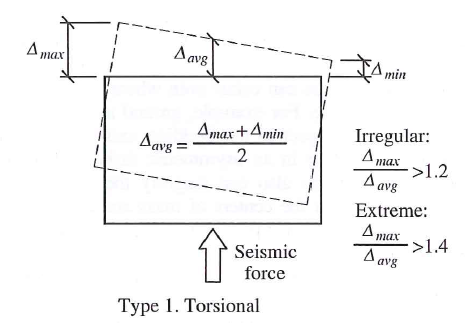 |
| 1b | Extreme Torsional Irregularity - Same as above but for maximum drift that is 1.4x the average drift | 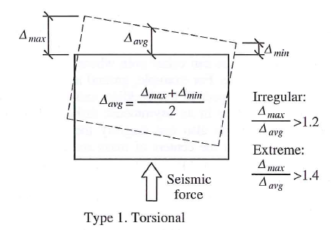 |
| 2 | Reentrant Corner - L-shape floor plan where the projection is > 15% of the plan dimension | 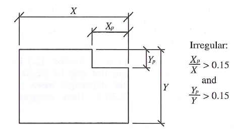 |
| 3 | Diaphragm Discontinuity - Large opening in floor plate with open (or flexible) area > 50% of the entire enclosed area | 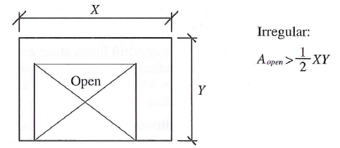 |
| 4 | Out-of-Plane Offset - Vertical element of SFRS is discontinuous vertically and shifts to another grid line | 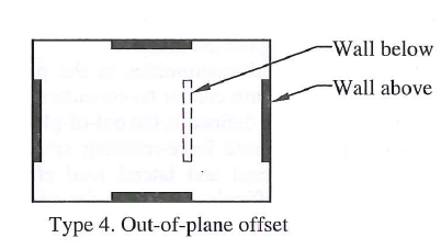 |
| 5 | Nonparallel System - Vertical element of SFRS is not orthogonal to each other | 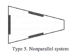 |
Vertical Irregularities
| Type | Description | Illustration |
|---|---|---|
| 1a | Soft Story - related to STIFFNESS. Exists if the story stiffness if less than 70% of the story above, or less than 80% of the average stiffness of 3 stories above | 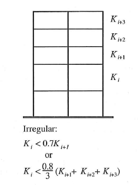 |
| 1b | Extreme Soft Story - Same as above, but replace the first and second percentage by <60% and < 70%, respectively. | 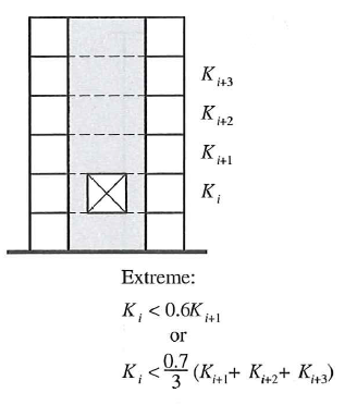 |
| 2 | Mass Irregularity - When mass of one floor is significantly higher than others (>150%) | 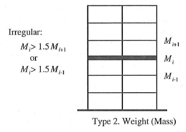 |
| 3 | Geometric Irregularity - When horizontal dimension of SFRS changes and one story is 130% of another | 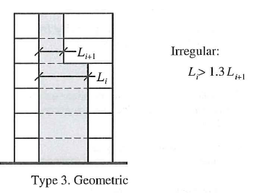 |
| 4 | In-Plane Offset - Offset of vertical element that creates a discontinuity in overturning | 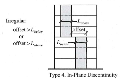 |
| 5a | Weak Story - related to STRENGTH. Exists if story strength (all SFRS elements) is < 80% of the story above | 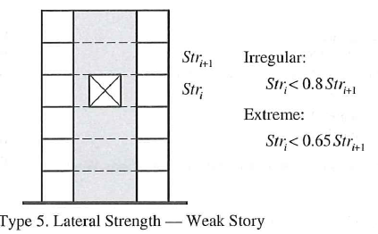 |
| 5b | Extreme Weak Story - same as above but change percentage to < 65% | 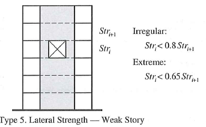 |
4.4 Procedure Selection and Modeling
Section 12.6 of ASCE 7-16 is related to analysis procedure selection. There are 3 types:
- Equivalent Lateral Force (ELF)
- Dynamic Analysis
- Modal Response Spectrum (12.9.1)
- Linear Response History (12.9.2)
- Nonlinear Response History (chapter 16)
- Simplified Procedure
Our emphasis will be mostly on the ELF and when it is permitted vs. not permitted. In summary:
- ELF always permitted for SDC = B or C
- ELF permitted unless structure has SDC = D, E, F and the following characteristics:
- Tall, long-period buildings. (height > 160 ft with \(T \geq 3.5 T_s\))
- Irregular structures < 160 ft if any of the following irregularities occur:
- Horizontal irregularity 1a, 1b
- Vertical irregularity 1a, 1b, 2, 3
12.7.1 - Foundation is permitted to be considered fixed for determining seismic load. Alternatively, see ASCE 7-16 chapter 19 for Soil-Structure Interaction (SSI)
12.7.2 - The following mass shall be included in the effective seismic weight (W):
- all dead load
- 25% of live load in storage area
- partition live load of 10 psf
- weight of any permanent equipment
- for snow load > 30 psf, include 20% of roof snow load
- weight of any landscaping
ASCE 7-16 has additional chapters and provisions for structures with base-isolation or special damping systems
- ASCE 7-16 Chapter 17 = Seismically Isolated Structures
- Isolation decreases base shear, increases natural period. Displacement response is not reduced but concentrated at the base
- Isolation is most effective for structures on dense/stiff soil
- ASCE 7-16 Chapter 18 = Structures with Damping Systems
- supplemental damping system absorbs damage and increases the damping ratio of the structure and hence a reduction in base shear
- Typically damping is achieved through inelastic action. Passive energy dissipation allows the damage to shift to dampers, greatly lowering retrofit cost post-earthquake
4.5 Equivalent Lateral Force Procedure (ELF)
Here are the steps for ELF:
- Construct design spectrum as shown in the previous chapter.
-
Calculate the short period (\(T_S\))(boundary of plateau)
\[T_S = \frac{S_{D1}}{S_{DS}}\] - Calculate seismic response coefficient which could fall into three regions
-
The plateau region
\[C_s = \frac{S_{DS}}{R/I_e}\] -
The tail region for moderately long period structure
\[C_s = \frac{S_{D1}}{T(R/I_e)}\] -
The region for extremely long period structures (extremely rare)
\[C_s = \frac{S_{D1}T_L}{T^2 (R/I_e)}\]
-
-
Calculate minimum \(C_s\) and determine governing value
\[C_{s,min1} = 0.044S_{DS}I_e \geq 0.01\] -
For structures with \(S_1 > 0.6\), there is a second minimum value to check:
\[C_{s,min2} = 0.5S_1 / (R/I_e)\] -
For short-period, very regular building less than 5 stories, there may be a potential to reduce Cs. See ASCE 7-16 12.8.1.3
-
Base shear is equal to the following. Don’t forget to check Cs,min
\[V = C_s W\] -
Story force is distributed vertically as follows:
\[F_x = C_{vx}V\] -
The distribution factor can be determined using this equation
\[C_{vx} = \frac{w_x h_x^k}{\sum w_i h_i^k}\]The exponent “k” is supposed to take into account the “whipping” effects of higher order modes
\[k = \left\{ \begin{array}\\ 1 & \mbox{if } T \leq 0.5s \\ 2 & \mbox{if } T \geq 2.5s \\ 0.75 + 0.5T & \mbox{otherwise} \end{array} \right.\] - Story shear (\(V_x\)) is simply the summation of story forces above. Story overturning moment (\(OTM_x\)) is simply the summation of moment at any particular level
4.6 Period Determination
- T = building fundamental period determined through analysis model
- Ta = approximate building fundamental period determined using empirical equations
12.8.2 - There is an upper limit on the period that you can use for analysis
\[T < C_u T_a\]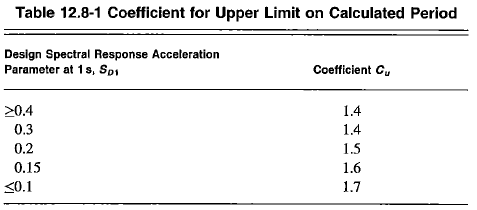 Figure 8: Cu Factor For Upper Limit Period
12.8.2.1 - The approximate period is mostly a function of building height:
\[T_a = C_t h_n^x\]The parameter (Ct,x) can be found in the table below and is SFRS dependent. \(h_n\) is the structure height.
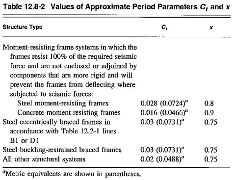 Figure 9: Parameters for Approximate Period Determination
4.7 Story Drifts, and Separations
Deflection of a Level
Deflection is the absolute displacement relative to the ground, at the center of mass of the floor.
\[\delta_x = \delta_{xe} \times \frac{C_d}{I_e}\]\(\delta_{xe}\) is the displacement from an elastic analysis, which must be amplified for inelasticity
Story Drift
Drift is the relative displacement between two adjacent stories:
\[\Delta_x = \delta_{x} - \delta_{x-1}\]Interstory drift ratio (IDR) is the story drift divide by the story height. The typical limit is around 2%. ASCE 7-16 Table 12.12-1 provides the allowable story drift limits.
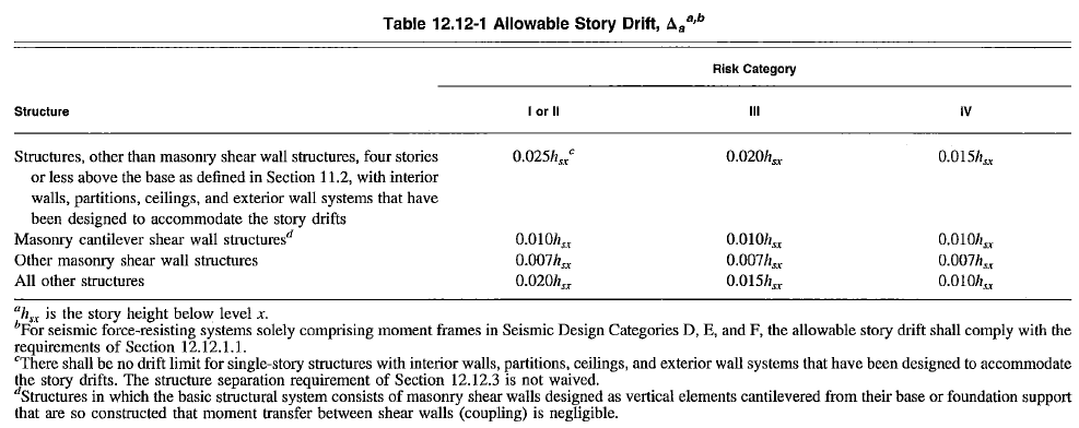 Figure 10: Story Drift Limits
Special Note When Calculating Drift
- 12.3.4.1 - \(\rho\) factor can be taken as 1.0 for drift calculations. Only exception is for moment frame with SDC = D to F (see 11.12.1.1)
- 12.8.6 - Drift should be based on Strength Design (LRFD) level loads
- 12.8.6 - For structure with torsion irregularity, drift is calculated as the most severe between two vertically aligned points along edge of floor plate
- 12.8.6.2 - The upper limit period (\(C_u T_a\)) need not be considered for drift calculations
Stuctural Separation (Seismic Isolation Joint)
Adequate spacing must be provided between buildings in close proximity to each other. Otherwise, pounding may occur. This is especially dangerous if the floors do not align, in which case collision could result in catastrophic column failure.
- 12.12.3 - The minimum separation is calculated based on the “maximum inelastic response displacement” (\(\delta_M\)) considering the maximum displacement on the floor (translation + torsion)
where \(\delta_{max}\) is the maximum displacement on floor x with Ax = 1 (no torsion amplification)
- 12.12.3 - For two buildings on the same property line, the minimum clearance between them should be the Square Root Sum of Squares of the two building’s maximum displacements
- For structures on different property lines, the building must be setback at least \(\delta_M\) from the property line
4.8 P-Delta, Stability, Orthogonal Effects, and Other Considerations
P-Delta and Stability
P-Delta is the development of secondary forces due to excessive lateral deformation. In ASCE 7-16, the intent of this provision is to ensure stability. Structures with very small lateral stiffness could have stability issues.
12.8.7 - First calculate the stability coefficient (\(\theta\))
\[\theta = \frac{P_x \Delta_x I_e}{V_x h_{sx} C_d}\]\(P_x\) is usually determined via drawing a large section cut, or sum up all column forces to account all vertical load at level x
\(h_{sx}\) is the story height, \(\Delta_x\) is the design story drift, \(V_x\) is the story force
In essence, the stability coefficient is a ratio of moment due to vertical load vs. moment due to lateral load
\[\theta = \frac{M_p}{M_v}\]- P-delta effect can be ignored if \(\theta < 0.1\) (i.e. secondary moment is less than 10% of that induced by lateral force)
- Otherwise, displacement and member forces must be amplified by the following factor
- if \(\theta > \theta_{max}\), the structure is unstable and must be redesigned. \(\beta\) is the ratio of shear demand to shear capacity between level x and level x-1. It can be conservatively taken as 1.0.
- If the analysis software already takes into account geometric nonlinearity (second-order analysis), the \(\theta_{max}\) must still be checked, but can divide \(\theta\) by \((1-\theta)\) before comparing to the limit.
Orthogonal Effects
For structures with nonparallel system irregularity:
- If SDC = B, can apply seismic force orthogonally independently
- If SDC = C:
- Can apply simultaneous orthogonal ground motion with response history analysis
- Alternatively, apply 100% seismic force in one direction, and 30% seismic force in the orthogonal direction with all permutation of directions for a total of 8 load combinations (100X+30Y, -100X+30Y, 100X-30Y, -100X-30Y, 30X+100Y, -30X+100Y, 30X-100Y, -30X-100Y)
- If SDC = D, E, F, same as above, but the condition of orthogonal effects are triggered if any column is part of both orthogonal systems
Other Considerations
12.12.5 - For SDC = D,E,F, components not part of SFRS (such as gravity columns) should be designed to withstand at least the compatibility force arising from interstory drift (\(\Delta\))
12.12.4 - For elements spanning between two structures, their connection must be designed for the maximum anticipated relative displacement, and assuming
- structures moving in opposite direction and using the absolute sum of their displacements
- consider diaphragm displacement
- consider torsional amplification factor
- calculate maximum displacement as shown:
4.9 Seismic Load Effect and Combinations
Seismic Load Effects - 12.4.2
- Horizontal seismic effect (\(E_h\)) - subject to redundancy or overstrength factor
- Vertical seismic effect (\(E_v\)) (can be neglected for SDC = B)
LRFD Load Combination - 2.3.6
- Full: \(1.2D + 1.2F + 1.0E + f_1 L + 1.6H + f_2 S\)
- Simplified: \((1.2 + 0.2S_{DS}) D + 1.0 \rho Q_E\)
- Full: \(0.9D + 0.9F + 1.0E + 1.6H\)
- Simplified: \((0.9 - 0.2S_{DS}) D + 1.0\rho Q_E\)
ASD Load Combination - 2.4.5
- Full: \(D + H + F + 0.7E\)
- Simplified: \((1 + 0.14S_{DS}) D + 0.7 \rho Q_E\)
- Full: \(D + H + F + 0.75(0.7E) + 0.75L +0.75S\)
- Simplified: \((1 + 0.105S_{DS}) D + 0.75( 0.7 \rho Q_E)\)
- Full: \(0.6D + 0.6F + 0.7E + H\)
- Simplified: \((0.6 - 0.14S_{DS}) D - 0.7\rho Q_E\)
\(F\) = fluid load
\(L\) = live load or roof live load > 20 psf
\(S\) = snow load
\(f_1\) = 1.0 for public assembly with 100 psf +, or parking garage. Equal to 0.5 for other live loads
\(f_2\) = 0.2 for typical roof. 0.7 for roof that does not shed snow
Overstrength Factor - 12.4.3.1
Where overstrength factor (\(\Omega_o\)) needs to be applied, the seismic effect is denoted as:
\[E_{mh} = \pm \Omega_o Q_E\]\(E_mh\) can be taken based on a capacity-approach (i.e. demand need not exceed what can be developed in the load path)
The load combinations with overstrength factor is the same as above, simply replace \(\rho\) with \(\Omega_o\)
Instances where omega factor needs to be applied:
- Collector elements and their connections (more on this in chapter 7)
- Element supporting discontinuous wall or frame (out-of-plane and in-plane offset)
- Cantilever column SFRS foundations overturning
Redundancy Factor - 12.3.4
Redundancy factor (\(\rho\)) is an indicator of how many redundant load paths are available. Buildings with multiple small SFRS tend to perform better than buildings with few large SFRS.
- redundancy factor (\(\rho\)) can be either 1.0 or 1.3. A value of 1.3 is assigned to be punitive against structures with low redundancy.
- Redundancy check is performed in both orthogonal directions
The value of \(\rho\) is permitted to be taken as 1.0 for all of these cases:
- SDC = B or C
- Other specific design checks like calculating drift, p-delta check, design of non-structural components (Fp), nonbuilding structures not similar to buildings, collector elements and their connections where \(\Omega_o\) is used, diaphragm load (Fpx), structure with damping system, out-of-plane wall force and anchorage.
For SDC = D, E, or F, \(rho = 1.3\) unless one of the following can be proven:
- Structure with no plan irregularity on all levels and:
- At least two bays of SFRS along perimeter framing in each orthogonal direction
- each story resists > 35% of base shear
- For shear walls, the number of bays can be calculated as \(L_{wall} / h_{story}\). (multiply by 2 for light-frame shear walls)
- Otherwise, depending on the system, conditions in ASCE 7-16 Table 12.3-3 must be proven
- Essentially, we must prove that the loss of a beam, wall pier, brace, etc. does not have an outsized effect on the building’s overall performance (more than 33% reduction in story strength, and no extreme torsional irregularity)
- The removal of elements should only be done on levels with story shear > 35% of base shear
4.10 Simplified Procedure
Refer to ASCE 7-16 12.14 for the complete list of provisions. Since the use of simplified procedure is not common in California, we will only summarize the key points here.
In essence, simplified procedure is only applicable for very regular, low-risk buildings:
- Risk category I, or II. Site class A, B, C, D, not more than 3 stories
- Cannot be dual system or moment frame
- In-plane and out-of-plane offset not allowed
- Various diaphragm requirements
- and a few others
Note that \(R\) factor shall be determined from a separate table specifically dedicated to simplified procedure (Table 12.14-1)
Seismic Design Category
12.14.8.1 - \(S_{DS}\) shall be calculated as
\[S_{DS} = \frac{2}{3} F_a S_s\]where:
- \(S_s\) is a ground motion parameter and need not exceed 1.5
- \(F_a\) is equal to 1.0 for rock site and 1.4 for soil site
Use this \(S_{DS}\) to determine the appropriate SDC.
Base Shear (V)
\[V = \frac{F S_{DS}}{R}W\]where:
- \(F\) equals 1.0 for one story building, 1.1 for two-story, 1.2 for three-story
- \(R\) is obtained from the specialized simplified procedure table 12.14-1
Vertical Distribution (Fx)
The seismic story force is simply proportional to the floor mass.
\[F_x = \frac{w_x}{W}V\]5.0 Seismic Provisions for Nonstructural Components
5.1 General Requirements
The following is a summary of ASCE 7-16 Chapter 13 which contains provisions related to seismic anchorage design of non-structural components such as mechanical/electrical equipment, pipes, architectural features, cladding, etc.
13.1.3 - Component importance factor (\(I_p\)) shall be taken as 1.0 unless the following applies, in which case take 1.5 (known as designated seismic systems)
- Component is required to function post-earthquake, such as sprinklers, egress stairs, etc.
- Component contains highly toxic or explosive substance
- Component is in a Risk Category IV building and its failure could impede proper operation
- Component contains other hazardous substances
13.1.4 - The following components need not be designed for seismic anchorage
- Furniture, temporary or moveable equipment
- Architecture component (except parapets) in SDC = B provided \(I_p = 1.0\)
- M&E equipment in SDC = B
- M&E equipment in SDC = C, provided \(I_p = 1.0\) or is less than 20 lbs (or 5 lbs/ft)
- M&E equipment in SDC = D, E, F provided that:
- less than 400 lbs with center of mass less than 4 ft AFF, component importance factor of 1.0, and flexible connection provided to the unit
- or it’s a distribution system weighing less than 5 lbs/ft, or discrete unit weighing less than 20 lbs
5.2 Seismic Demand
13.3.1.1 - the component seismic design force can be calculated as
\[F_p = 0.4 (\frac{a_p}{R_p / I_p}) (1 + \frac{2z}{h}) S_{DS} W_p\]subject to the following maximum and minimum values
\[F_{pmax} = 1.6 S_{DS} I_p W_p\] \[F_{pmin} = 0.3 S_{DS} I_p W_p\]where:
- \(a_p\) is the component amplification factor (which accounts for flexibility of equipment and resulting dynamic amplification. 1.0 for rigid, 2.5 for highly flexible)
- \(R_p\) is the component response modification factor (which accounts for equipment’s inherent ductility)
- \(W_p\) is the component weight
- \(I_p\) is the component importance factor
- \(z\) is the height in elevation of component’s point of attachment
- \(h\) is the height of the building (not including any parapet!)
The z/h ratio essentially dictate an amplification of 1.0 at ground, and 3.0 at the roof.
The \(F_p\) force is applied at component’s center of gravity and shall be applied independently in at least two orthogonal horizontal directions
The component parameters (\(a_p, R_p, \Omega_p\)) for an exhaustive list of components can be found in ASCE 7-16
- Mechanical and electrical: Table 13.6-1
- Architectural: Table 13.5-1
5.3 Miscellaneous Requirements
13.3.1.2 - vertical seismic effect (\(E_v = 0.2 S_{DS}\)) should be considered in design. Redundancy factor is taken as 1.0
\(\Omega\) factor shall be applied when designing non-ductile anchorage into concrete or masonry. Please note this omega factor is NOT from chapter 12 and should be determined from Table 13.5-1 or 13.6-1
13.4 - frictional effect by gravity should not be considered in design.
13.3.2 - seismic relative displacement should be considered in design (i.e. interstory drift displacement compatibility)
Other specific provisions:
- 13.5.7 - Access floors
- 13.5.8 - Partitions
- 13.5.9 - Glass
- 13.5.10 - Egress stair and ramps
- 13.6.5 to 13.6.8 - Distribution systems: Ducts, conduit, cable trays, pipes, tubes, trapezes
- 13.6.10 - Boilers and pressure vessels
- 13.6.11 - Elevators
- 13.6.12 - Roof top solar
5.4 Out-of-Plane Wall Anchorage
Out-of-plane walls also have to be anchored adequately to the diaphragm. This is usually not an issue for concrete and structural steel buildings, but is supremely important for masonry + wood buildings where past experience has shown some vulnerabilities (especially for tilt-up structures).
12.11.1 - Out-of-plane wall bending design force
\[F_p = 0.4S_{DS} I_e W_w \geq 0.1 W_w\]12.11.2 - Wall anchorage design force is similar with some additional factors to account for flexible diaphragm action
\[F_p = 0.4 S_{DS} K_a I_e W_p \geq 0.2 K_a I_e W_p\]- Wall weight is usually given in plf. Multiply by tributary width (anchor spacing) to get weight of wall tributary to anchor (\(W_p\)). Make sure to include weight of parapet if applicable
- Diaphragm flexibility factor (\(K_a\)) is calculated based on the diaphragm span (\(l_f\)) in feet. Use 1.0 for rigid diaphragms
- If the anchorage is not located at the roof and all diaphragms are rigid or semi-rigid, then the calculated force can be modified by the following factor
Some Other Wall Anchorage Considerations - 12.11.2.2
- Sub-diaphragms shall has max aspect ratio of 2.5:1
- The design force shall be amplified by 1.4 for steel strap purlin anchors
- Metal deck should not be considered as continuous ties
- Toenails and nail withdrawal are not permitted for anchorage
- Toenails are nails driven at an angle. Use framing clips instead (e.g. Simpson Strong Ties L/LS/GA)
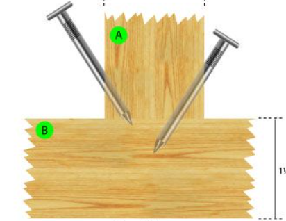
- Ledgers are not permitted to be in cross-grain bending/tension (typical for tilt-up)
- Ledger basically splits apart. User purlin anchors instead (x1.4 amplification) (e.g. Simpson Strong Ties PA/HPA)
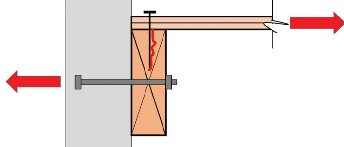
- For wood design, remember that force level has to be converted to ASD level (i.e. multiply by 0.7)
6.0 Seismic Provisions for Nonbuilding Structures
This chapter is a summary of provisions from ASCE 7-16 Chapter 15 which is related to non-building structures (e.g. elevator tanks, chimneys, silos, telephone towers, signs, monuments).
11.1.2 - Some nonbuilding structures have their own code and regulations such as highway bridges, transmission tower, hydraulic structures, buried utility lines, and nuclear reactors.
15.3 - For nonbuilding structures supported by a building. Such as penthouse, helipad, etc.
- Less than 25% of weight - Design as non-structural component (chapter 13)
- More than 25% of weight - The supported structure should be modeled within the main building model
Nonbuilding Structure - Rigid
15.4.2 - Rigid nonbuilding structures are those with period (T) less than 0.06 seconds, for these situations, the base shear is calculated as follows. Vertical force distribution is calculated in the typical way.
\[V = 0.30 S_{DS} W I_e\]Nonbuilding Structure - Similar to Buildings - 15.5.1
Applies to structures that behave and is constructed like buildings and have SFRS like buildings (e.g. storage racks, towers for tanks and vessels, piers, pipe racks). All of these will have their special provisions as well within chapter 15
15.5.1 - Use the same equations from ELF, except the seismic parameters (\(R,\Omega_o,C_d\)) should be determined from Table 15.4-1
Nonbuilding Structure - Not Similar to Buildings - 15.6
Applies to structure that are significantly different from buildings and do not have a dedicated SFRS. (e.g. silos, stacks, cooling tower, rollercoaster rides, signs and billboards, etc)
- The seismic parameters (\(R,\Omega_o,C_d\)) shall be determined from Table 15.4-2. These parameters are generally more conservative because of the inherent lower redundancy
- Use the same set of equations from ELF with the following modification for minimum value (eq 15.4-1). Note the second equation is only applicable for non-building structure where S1 > 0.6.
For this category of structures, there are usually additional provisions within ASCE 7-16 that are relevant. For example, the design of tanks and vessels require the consideration of fluid-structure interaction.
- Rigid forces (from impulsive fluid mass)
- Sloshing forces (due to convective fluid mass from ground motion)
7.0 Diaphragm and Walls
The following chapter contains provision from various chapters of ASCE 7-16 (mostly chapter 12). The main topic of discussion is related to diaphragms (seismic load path). Topics will include diaphragm design forces, horizontal SFRS elements, diaphragm types, and torsion/wall rigidity considerations.
7.1 Diaphragm Design Force
12.10.1.1 - The standard ELF vertical story force distribution, which is based on the first mode, tends to underestimate required diaphragm design force (which might peak at other modes). Therefore, the diaphragm design force is calculated separately as follows:
\[F_{px} = \frac{\sum_{i=x}^{n} F_i}{\sum_{i=x}^{n} w_i} w_{px}\]Subject the following maximum and minimum:
\[F_{pxmin} = 0.2S_{DS}I_e w_{px}\] \[F_{pxmax} = 0.4S_{DS}I_e w_{px}\]Note that the summations are from the floor under consideration to the roof.
Also note on distinction between \(w_{px}\) and \(w_x\) from ELF distribution. These two terms do not necessary have to be equal, but are often assumed to be equal for simplicity (also because it is conservative). Technically mass of walls parallel to direction of analysis does not need to be counted since they do not contribute to diaphragm demand. An analogy would be applying point load at a support point.
7.2 Diaphragm Provisions
12.10.3 - Precast diaphragms in structures assigned to SDC = C,D,E,F must use the alternative diaphragm design procedure in 12.10.3.1
12.3.1 - Diaphragms may be of three types:
- flexible diaphragm - SFRS attracted load is in proportion to its tributary width. No need to consider torsion
- rigid diaphragm - SFRS attracted load is in proportion to its rigidity
- semi-rigid diaphragm - somewhere in between
12.3.1.1 - Flexible diaphragm condition can be assumed for un-topped steel deck and wood structural panels if specific conditions of this provisions are met (in brief: if the SFRS is stiff, structure is small and light)
12.3.1.1 - Flexible diaphragm can also be assumed if the maximum diaphragm displacement is more than twice the average diaphragm displacement
\[\Delta_{max} > 2 \times \Delta_{avg}\]7.3 Diaphragm Analysis - Collector and Chords
Regardless of what type of diaphragm you have, and how you scale the design forces. The big picture is that we are trying to check the adequacy of our SFRS horizontal element under the following conditions:
- Diaphragm shear (unit shear demand = V/d)
- Diaphragm moment (chord force = M/jd)
- Collector axial demand (drag force)
Limit state 1 and 2 is typically done through finite-element analysis for more complex models. For simpler buildings, it is common to use the equivalent beam method.
Limit state 3 (determining drag force) is more of a local check and can be performed separately from the other checks above.
Equivalent Beam Method - Diaphragm Shear and Moment Analysis
 Figure 11: Equivalent Beam Model
In essence, the equivalent beam method involve plotting the shear and moment diagram of a beam. This step can actually be quite nuanced but we will table that discussion for another article. For now, let’s assume a simply-supported beam.
- determine the correct diaphragm design force (Fpx)
- divide by span to obtain a uniform load (w)
- plot shear and moment diagram (M, V)
- diaphragm shear capacity is usually provided in lbs/ft. Divide shear by diaphragm depth (V/d)
- diaphragm chord force can be determined by dividing moment by diaphragm depth (M/jd). “j” is a lever arm factor to reduce the lever arm if you expect the resultant axial force to be elsewhere and not at the edge.
Diaphragm shear is resisted through:
- Steel and concrete buildings: Concrete slab (or slab on deck) (Vc can be determined per ACI 318)
- Wood buildings: plywood sheathing or other panels with nails (capacity usually tabulated in code and design aid)
Diaphragm chord force is resisted through:
- Steel & wood building: perimeter (spandrel) beams (check for seismic axial + gravity moment interaction per AISC 360)
- Concrete building: Rebar + an assumed concrete section (check capacity per ACI 318. Additional guidance is available through NEHRP Tech Briefs)
Determining Drag Force
As mentioned previously, collector drag force diagram can be determined independently from the analyses above. Before diving into the analysis, here is the answer to some frequently asked questions:
- “why do we need collectors anyways?”
- Consider the illustration below. Without adequate collector connection, it is conceivable that the inertial mass at the lower half of the slab will pull apart (see red cracks)
- Occasionally, partial-depth collector are necessary due to constraints, but that is a complex topic that we wil table for another day. For partial depth collectors, the diaphragm depth is effectively reduced, increasing your shear and chord force demand.
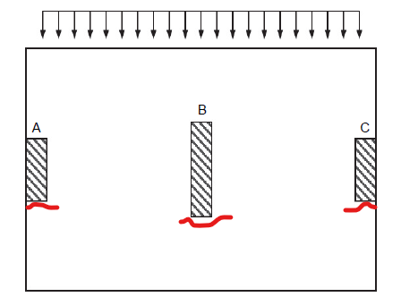 Figure 12: Inadequate Collectors or Partial Depth Collectors
- “Why not just pull collector axial demand from the model”
- This is a very complex topic and is not well-researched. Without diving too deep, just know that it is not as easy as extracting forces from an analysis model. Firstly, it is simply a non-starter for rigid-diaphragms. Even if it were possible in the case of semi-rigid and flexible diaphragms, there are numerous modeling considerations to incorporate (such as softening surrounding beams, reducing axial stiffness modifier for slab shell elements along frame line, etc). Ultimately, the amount of possible load path is simply unlimited (as the diaphragm is literally connected to everything). As such, our task is not the design for the correct load path, rather it is to design for one feasible load-path out of many; as long as the assumptions are rational. Naively reading axial demand from a model will likely lead to an under-prediction of axial demand.
- “Why is collector/diaphragm analysis so complicated?”
- Because the typical intro to diaphragm design uses simple examples with square buildings and perfect slab layout. Unfortunately, those buildings rarely exist. And the equivalent beam procedure extends terribly to more complicated situations.
- Because most diaphragms are rarely damaged post-earthquake. It has never really been emphasized by building codes and design references. Because of the lack of attention, your best resource becomes design guides and conference papers, which lends itself to more assumptions and engineering judgement.
Think of collectors as extending your frame or wall to incorporate the entire frame line from one edge of the slab to the other. If your frame or wall extends the entire length of the building, then collectors are not required. The procedure for plotting drag force diagram is as follows:
- First, create section cuts above and below the diaphragm level under consideration
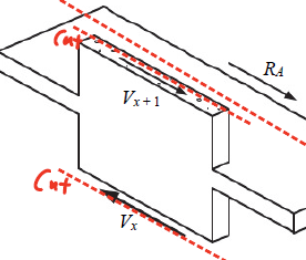 Figure 13: Section Cut Above and Below
 - The difference in story shear above and below is the amount of additional force that enters the frame line from the diaphragm level under consideration
- Think of the collector diagram as a column with uniformly-distributed axial load. Referring to the figure below, there are two uniform axial load being applied (\(w_1 = V / L_{wall}\) and \(w_2 = V / L_{total}\)). “w1” occurs over the length of the wall, whereas “w2” occurs over the entire frame line. Note that “w1” and “w2” acts in opposite directions.
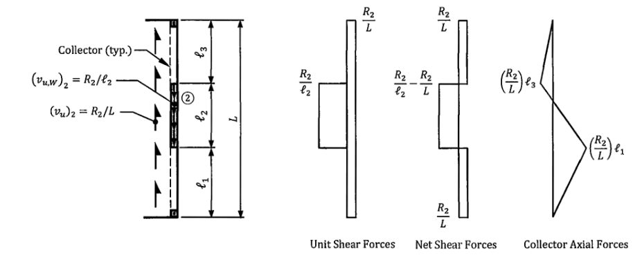 Figure 14: Determining Drag Force
Collector drag force is resisted through:
- Concrete buildings: Rebar and assumed concrete section (check capacity per ACI 318. Additional guidance is available through NEHRP Tech Briefs)
- Steel & wood buildings: Steel or wood beams along the frame line (check for seismic axial + gravity moment interaction per AISC 360)
12.10.2.1 - This is a common “gotcha” clause in ASCE 7-16 that is also incredibly confusing. Essentially, collectors and their connections should be designed to “omega-level” force, which may not always be as simple as multiplying demand by omega. The omega-level force is defined as the maximum of:
- ELF story force multiplied by omega (\(F_x \times \Omega_o\))
- Diaphragm story force multiplied by omega (\(F_{px} \times \Omega_o\))
- Floor diaphragm force NOT multiplied by omega, as it is not a function of R (\(F_{pxmin}\))
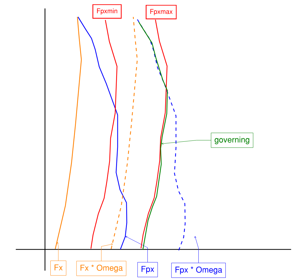 Figure 15: Collector Design Force Scaling Example
7.4 Flexible Diaphragm Analysis
Forces entering a lateral line for a flexible diaphragm is determined simply by its tributary width. Torsion is not considered.
7.5 Wall Rigidity
Before diving into rigid diaphragm analysis, we need to first understand wall rigidity. The stiffness of any wall pier can be calculated as follows. Note the inclusion of shear deformation which is critical for walls:
\[k_{fix-fix} = \frac{12EI}{L^3} + \frac{A_v G}{L}\] \[k_{fix-pin} = \frac{3EI}{L^3} + \frac{A_v G}{L}\]- \(A_v\) is the effective shear area (equal to 5/6 of gross area for rectangular sections)
- \(G = E / 2(1+v)\) is the shear modulus and is a function of a material’s Young’s modulus and Poisson ratio (v)
- Do not include height of parapet in stiffness calculation
In any situation where displacement compatibility is enforced (such as rigid diaphragm, or multiple wall pier along same wall line), for the same amount of displacement, the amount of force resisted by each wall pier can be determined as:
\[F_i = F_{total} \times \frac{K_i}{\sum K_i}\]Refer to the Appendix for a helpful table for quick determination of wall stiffness based on h/L ratio.
7.6 Rigid Diaphragm Analysis + Torsion
Within a rigid diaphragm, the center of mass and the center or rigidity often do no coincide. In these situations, an additional “twist” or in-plane torsional arises that may amplify forces going into particular lateral lines.
The ultimate goal of this chapter is to determine these amplified forces. But first we must understanding how center of mass (COM) and center of rigidity (COR) is calculated.
Center of Mass
Center of mass is self-explanatory and it is a function of the distribution of weight on a particular level. Most of the times, the floor area center is very close to the COM.
It can be calculated by discretizing the mass into numerous segments. \(x_i,y_i\) is the distance between centroid of a segment to a reference datum. The story force can be assumed to be concentrated at the center of mass.
\[X_{CM} = \frac{\sum W_i*x_i}{\sum W_i}\] \[Y_{CM} = \frac{\sum W_i*y_i}{\sum W_i}\]Refer to the Appendix for a helpful template table for calculating COM.
Center of Rigidity
Center of rigidity can be thought of as the center of resistance and will tend to be closer to the stiffer line of resistance. It can also be thought of as the center of rotation when the slab “twists”. The resulting force from this twist can be calculated using mechanics first principles (see polar moment of inertia).
Center of rigidity is calculated in a similar way to center of mass.
- X coordinate is calculated with NS walls
- Y coordinate is calculated with EW walls
Refer to the Appendix for a helpful template table for calculating COR.
12.8.4.1 - Inherent Torsion
Inherent torsion is the torsion that arises from the eccentricity between CoM and CoR. Structures are usually toned to minimize inherent torsion.
\[e_x = X_{CM} - X_{CR}\] \[e_y = Y_{CM} - Y_{CR}\]12.8.4.2 - Accidental Torsion
Accidental torsion is a code-specified minimum torsion that must be considered due to potential mass irregularities from occupancy and floor usage. For example, one part of the building may be used for storage, while another used for open floor space. The current code minimum is +-5%.
Conceptually, accidental torsion shifts the center of mass, but this is just a semantic exercise since the resulting effect is the same.
Accidental torsion only applies to the following scenario. In all other cases, it can be ignored:
- SDC = B with extreme torsional irregularity
- SDC = C,D,E,F with any torsional irregularity at all
Furthermore, for SDC = C,D,E,F with any torsional irregularity, the effect must be amplified:
\[A_x = 1.0 \leq \left[ \frac{\delta_{max}}{1.2\delta_{avg}} \right] ^2 \leq 3.0\] \[e_x = \pm A_x \times 0.05 L_x\] \[e_y = \pm A_x \times 0.05 L_y\]- both max and average displacement is calculated based on the corner nodes of the building
Final Design Force At Each Frame
With all things considered, the resulting torsional moment can be calculated:
\[M_{Tx} = V_x \times (e_y \pm 0.05 A_x L_y)\] \[M_{Ty} = V_y \times (e_x \pm 0.05 A_x L_x)\]Only apply accidental torsional and amplification where required. It should also be noted that since earthquake forces, as well as accidental torsion offset can be in both the positive and negative direction, always design for the worst case scenario in each frame.
Finally, the forces in each frame is calculated as follows:
\[F_{i} = \mbox{direct shear} + \mbox{torsional shear}\] \[F_{i} = F_{story} \frac{K_i}{\sum K_i} + M_T \frac{K_i e_i}{J_r}\]- \(e_i\) is the perpendicular distance of a wall to the COR
- \(J_r\) is the polar moment of inertia and is calculated for all walls both parallel and perpendicular to direction of analysis
8.0 Wood Diaphragms and Shear Walls
I find it quite peculiar that this is included in the California State seismic PE exam. In this chapter, we will discuss the design of wood diaphragms and wood shear walls. Most of the provisions will be from IBC and the American Wood Council SDPWS-2015 (special design provisions for wind and seismic).
8.1 General Provisions
Wood design is primarily done in ASD. Always remember to multiply earthquake force by 0.7
\[D + 0.7E\]4.2.3 and 4.3.3 - The unit shear capacities (lbs/ft) provided in the diaphargm/shear wall design tables are nominal values and should be divided by 2 to obtain the design capacity.
- Diaphragm unit shear capacity is provided in SDPWS Table 4.2A to 4.2D
- Shear wall unit shear capacity is provided in SDPWS Table 4.3A to 4.3D
- SDPWS 4.1.5.1 - subdiaphragms shall have a max length-width ratio of 2.5:1
- SDPWS 4.1.5.1.1 - out of plane wall anchorage cannot be provided by nail withdrawal or toe-nails. The ledger must not be used for cross-grain bending or cross-grain tension
8.2 Wood Diaphragms
Wood diaphragms are typically constructed from panels of sheathing nailed together with the joists or rafters. At the free panel edges perpendicular to the joists, they can be left unconnected (unblocked), or a blocking can be provided underneath to join them together. Blocked diaphragms have higher capacity but is more expensive to build.
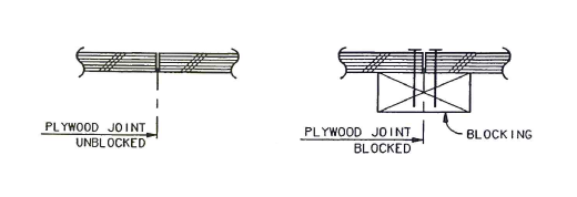 Figure 16: Blocked vs. Unblocked Wood Diaphragm
The design procedure for wood diaphragm is as follows:
- Calculate diaphragm design force and diaphragm shear
- Decide on type of panel and blocked or unblocked diaphragm
- From design table, select:
- panel thickness
- nail size
- nail spacing
- Confirm capacity > demand. Remember to divide capacity by 2, multiply demand by 0.7 for ASD
- Check other provisions related to blocked, unblocked diaphragms (aspect ratio, nailing pattern, etc)
4.2.4 - Wood diaphragms are limited to certain aspect ratio depending on the type.
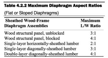 Figure 17: Limiting Diaphragm L:W Ratio
How To Read Diaphragm Capacity Table
- Table 4.2A = Blocked diaphragm
- Table 4.2B = Blocked diaphragm (High demand, multiple row fastener)
- Table 4.2C = Unblocked diaphragm
- Table 4.2D = Diagonal lumber diaphragm
Given the following parameters, enter a specific row:
- sheathing grade
- nail size with corresponding min fastening penetration
- sheathing panel thickness
- width of joist (nailed face of adjoining panel edge)
For design, pick a unit shear capacity (lbs/ft) that works, then look at the column which will inform you the required nail spacings for each loading case.
You can also obtain specific gravity values “Ga” which can be used for deflection calculations.
- If the specie of the framing members are not Douglas-Fir-Larch or Southern Pine (most common), then the capacity has to be modified by \(0.5+G\)
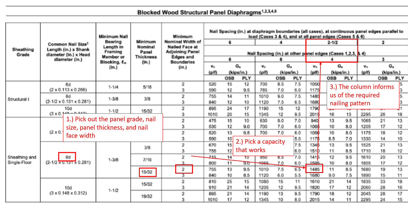 Figure 18: Diaphragm Design Table Example
The figure below shows the various type of loading cases.
- Pick a capacity from the design table that works
- The load cases help inform the nailing spacing required at various edge conditions:
- continuous panel joint parallel to framing will have spacing A
- continuous panel join perpendicular to framing will have spacing B
- diaphragm boundaries will have spacing C
- if panels are laid out like case 5&6, then will have spacing D
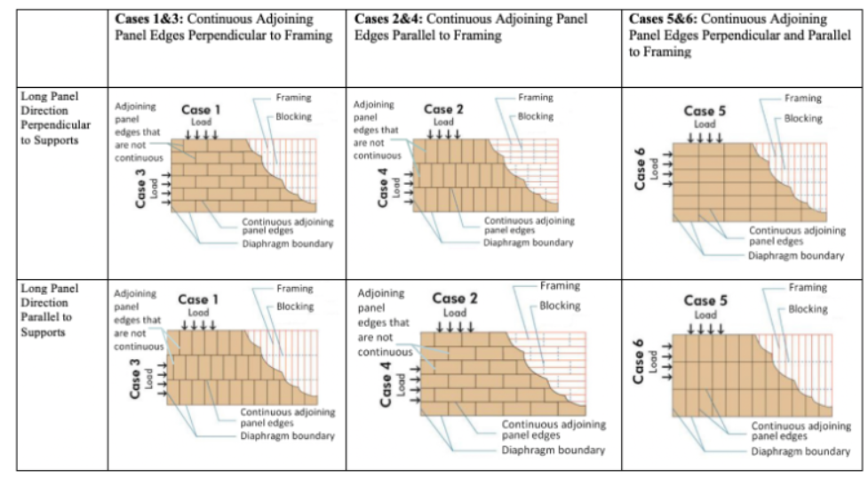 Figure 19: Diaphragm Loading Cases
Other Provisions - Blocked Diaphragm - 4.2.7.1.1
- panels should be 4 ft by 8 ft minimum except at boundaries or around openings. Minimum panel dimension is 24” unless its all the edges are supported and fastened
- nails 3/8” min. clearance from edge of panel. Panel edge nail max spacing = 6”. Within the panel itself, max nail spacing parallel to joist should be 6” for joists spaced 48” c/c, or 12” if joist is spaced closer. (change 48” limit to 32” for highly loaded blocked diaphragms)
- For highly-loaded blocked diaphragms, depth of framing member and blocking should be at least 3” nominal.
8.3 Wood Shear Walls
For shear wall design, remember that the seismic force has to be amplified by rho factor if appropriate:
\[0.7 \rho E_h\]Determining Shear Wall Unit Shear Capacity
- Table 4.3A = blocked shear wall
- Table 4.3B = blocked shear wall w/ gypsum board over it
- Table 4.3C = gypsum wall board shear walls
- Table 4.3D = diagonal lumber shear walls
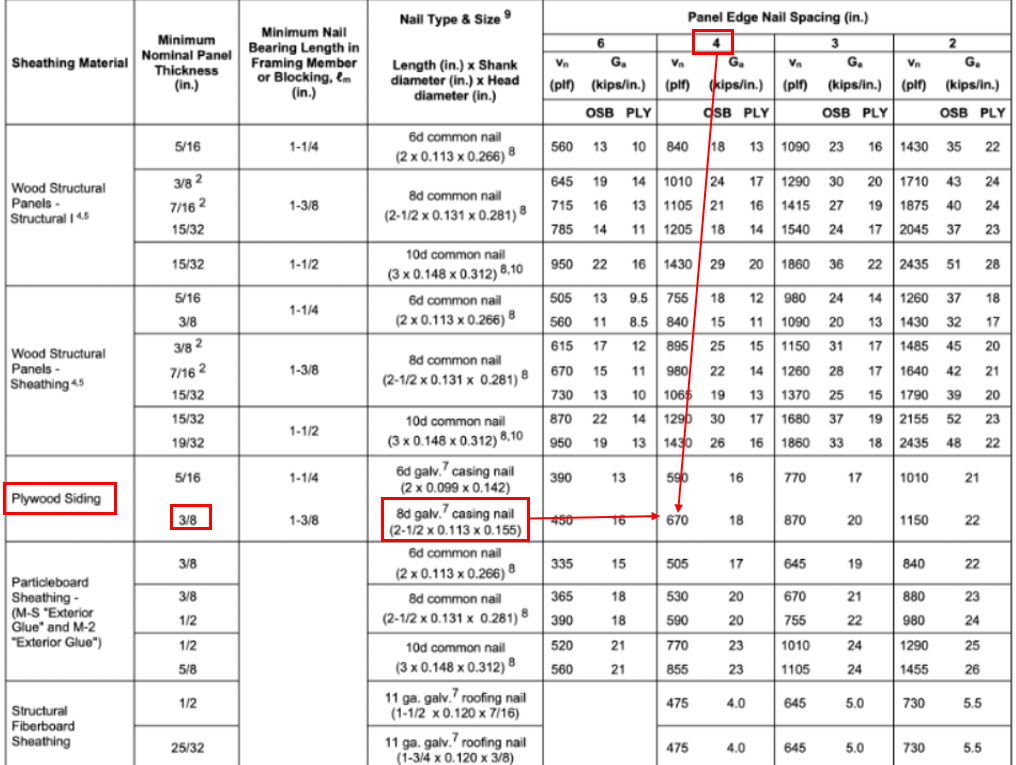 Figure 20: Diaphragm Design Table Example
-
If the specie of the framing members are not Douglas-Fir-Larch or Southern Pine (most common), then the capacity has to be modified by \(0.5+G\)
-
4.3.4.2 - WSP shear wall capacity determined above must be modified based on the wall’s aspect ratio. The aspect ratio factor (ARF) is equal to 1.0 if h/b is less than 2:1 (squat)
Adjustment Factors and Other Shear Wall Provisions
4.3.3.3 - If a wall is sheathed on both sides with the same material and nailing pattern. Can double the shear capacity.
4.3.3.2 - Unblocked shear wall cannot exceed 16 ft.
4.3.3.2 - The design tables provided by SDPWS is only for blocked shear walls. Unblocked shear wall capacity can be calculated using the equation below.
\[v_{ub} = v_b \times c_{ub}\]- \(v_b\) is the shear capacity (lbs/ft) of a blocked shear wall with 6” nail spacing from Table 4.3A
- \(c_{ub}\) is an adjustment factor from Table 4.3.3.2. Reproduced below.
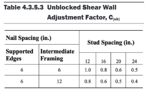 Figure 21: Unblocked Shear Wall Adjustment Factor
4.3.4.1 - Shear walls have limiting aspect ratios. Also note that there are specific requirements to each wall type. Some are prohibited in higher SDC categories.
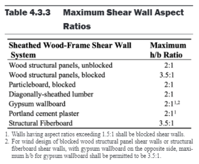 Figure 22: Aspect Ratio Limit for Shear Walls
4.3.3.4.1 - For shear walls piers along a same line, the force in each pier can be calculated based on stiffness. Alternatively, they can also be taken in proportion to their shear capacity if the capacities were determined such that any pier with h/b>2 was multiplied by 2b/h. No aspect ratio reduction needed for this.
There is also an overabundance of provisions for perforated wood shear walls that we will not go into here.
Shear Wall Overturning
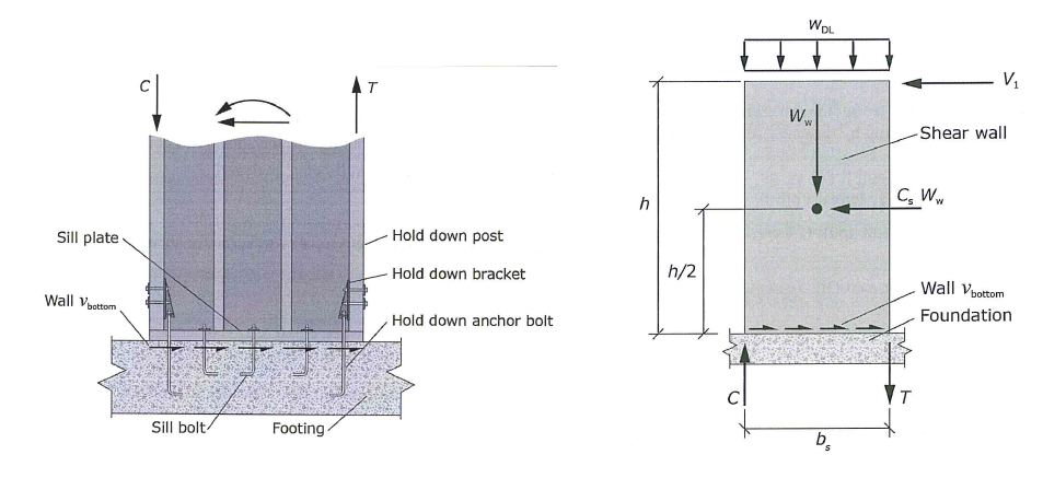 Figure 23: Shear Wall Overturning
Sill bolts resist shear, hold-down anchors resist uplift.
The overturning moment is calculated as:
\[M_{OT} = F_p \times \frac{h}{2}\]The resisting moment is calculated as:
\[M_R = W \times \frac{b}{2}\]The net moment and resulting uplift is calculated as:
\[M_{net} = M_{OT} - M_R\] \[T = M_{net} / b\]Note that the weight (W) and the seismic force (Fp) are subject to various ASD load combinations. The most-critical is the uplift load combination with vertical seismic effect:
\[(0.6 - 0.14S_{DS})D + 0.7 \rho E\]In wood design, sub-diaphragm is used to refer to a portion of floor area that brings out-of-plane wall force into the main diaphragm. The rationale for this is confusing. Since I am not a wood-design expert, I will not discuss that matter any further.
9.0 Miscellaneous. Inspections. Professional Engineers Act. Etc.
ASCE 7-16 12.13.4 - Foundation overturning stability can be reduced by 25% if using ELF, or 10% if using modal analysis. (Not applicable to inverted pendulum or cantilever structures). The rationale for this is because ELF assumes first mode behavior, but every floor accelerating in the same direction usually does not happen. So overturning moment is over-estimated at the foundation level.
IBC 1807.2.3 - Factor of safety (FS) for sliding and overturning stability of retaining walls should be no less than 1.5. For load combination including seismic forces, FS limit can be reduced to 1.1
Inspections
- Inspection by building official is required for these:
- footing, foundation
- slab and underfloor
- lowest floor elevation in flood hazard area
- framing
- dry wall
- fire-resistant penetrations
- energy efficiency
- other special inspections as needed
- final inspection
- Inspections may be periodic or continuous
- periodic - intermittent presence
- continuous - continuous presence when and where the work is being performed
- Structural observation by a registered design professional is sometimes required by IBC 1704.6 to confirm general conformance to construction documents. The structural observer need to inform the building official the frequency and extent of observation beforehand.
- Written statements have to be submitted to the building official identifying any deficiencies that have not been resolved.
Professional Engineers Act
- Practice Act - only a person licensed by the board may practice engineering
- Title Act - Only a person licensed by the board can claim to be an “engineer”
- The structural engineer of record (SEOR) has the “responsible charge of work”, meaning they exercise independent control and judgement over the project. A subordinate is any person who assists a registered PE without assuming responsible charge.
- Only those with SE license can claim to be a “structural engineer”. Only an SE can design
- public schools (DSA)
- hospitals (HCAI)
- buildings > 160 ft in LA county
- Non licensed individuals can prepare plans and drawings for the following specific scenario:
- single family building less than two stories
- agriculture, ranch, low-occupancy buildings
- timber framing garages less than two stories
Appendix: Helpful Tables and Other Stuff
Table For Wall Stiffness
The flexibilities (inverse of stiffness) from flexural displacement and shear deformation is as follows:
\[\mbox{fixed-fixed: } f_f + f_v = \frac{12H^3}{12tEL^3} + \frac{6H}{5tLG}\] \[\mbox{fixed-free: } f_f + f_v = \frac{12H^3}{3tEL^3} + \frac{6H}{5tLG}\]The expression above can be further simplified in terms of their H/L ratio:
\[\mbox{fixed-fixed: } f_f + f_v = \left[ 1t(H/L)^3 + 3t(H/L) \right] \times E^{-1}\] \[\mbox{fixed-free: } f_f + f_v = \left[ 4t(H/L)^3 + 3t(H/L) \right] \times E^{-1}\]Finally, the stiffness is simply the inverse of the above:
\[k = \frac{1}{f_f + f_v}\]- H = wall height, L = wall length, t = wall thickness
- Assuming effective shear area is equal to 5/6 of gross area
- Per ACI 318 and TMS 402, the shear modulus may be approximated as G = 0.4E
- Assuming same E and t for all walls
- Remember to not include height of parapet in stiffness calculations
Using the above derivation and assumptions, we can create a handy table to quickly look up wall stiffnesses:
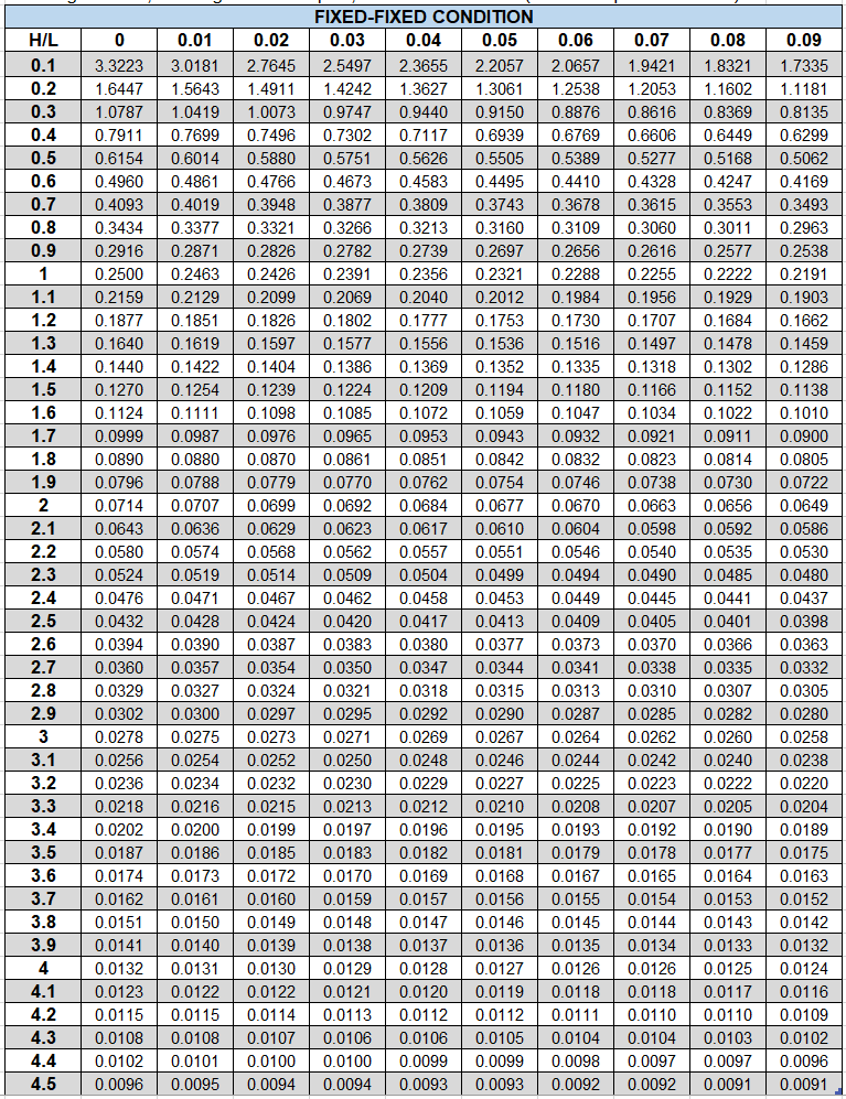 Figure 23: Shear Wall Stiffness - FIXED-FIXED
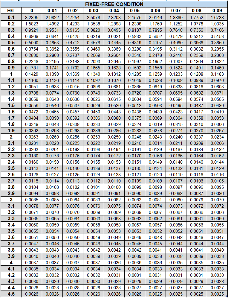 Figure 24: Shear Wall Stiffness - FIXED-FREE
Table Template for ELF Force Vertical Distribution and Diaphragm Forces
Below is a helpful table template for determining vertical story force distribution for ELF and also diaphragm design forces.
Other helpful tips:
- For diaphragm design (\(w_{px}\)): No need to include weight of in-plane wall because they resist themselves
- For ELF story force distribution(\(w_{x}\)): include weight of all walls tributary to that level (usually taken as half wall height above and below)
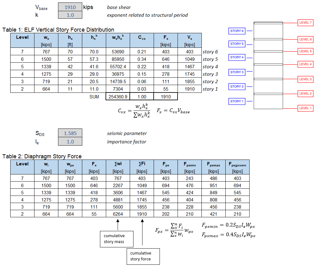
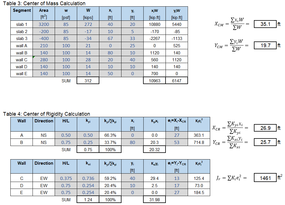
Table Template for Determining Center of Rigidity
Below is a helpful table template for determining center of mass, center of rigidity, and polar moment of inertia.
Other Helpful Tips:
- Center of rigidity is not applicable to flexible diaphragms
- When calculating center of mass of a floor, remember you can use negative area as well. Also make sure to include weight of wall tributary to the floor
- COR calculation:
- NS wall => Ky => xi
- EW wall => Kx => yi
Comments