Primer: ACI 318-19 Fundamentals
“Primers” are my personal notes on various technical topics in structural engineering. Building codes are dense and voluminous, sometimes written in legalese rather than in sentences that can be easily understood. I write these “Primer” so I can gather, organize, and condense technical topics I encounter as an engineer. Please understand I made these for myself. Reader discretion is advised. No warranty is expressed or implied by me on the validity of the information presented herein.
1.0 The Basics
1.1 Material Properties
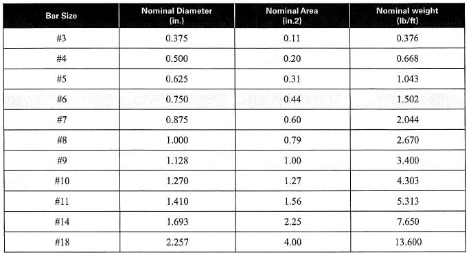 Table 1: Rebar Size Table
All empirical equations presented in ACI 318-19 will have unit [lbs, in, psi] unless otherwise noted.
Reinforced concrete is an inherently non-linear material. Nevertheless, we still model and analyze it linearly for convenience with the use of empirically derived equations and secant stiffness modifiers.
6.6.3.1.1 - Secant stiffness modifier are empirically determined. In some sense, it correlates to the degree of cracking and how much the element has “softened”. In lieu of more accurate analysis, the following modifiers can be used:
- columns: \(0.7EI_g\)
- beams: \(0.35EI_g\)
- walls (cracked): \(0.35EI_g\)
- walls (uncracked): \(0.70EI_g\)
- two-way slab:\(0.25EI_g\)
For service load analysis (deflection, vibration, etc), 6.6.3.2.2 suggests amplifying the above factor by 1.4
No reduction shall occur for area for axial deformation and shear deformation. Should more rigor be required, equations from 6.6.3.1.1 can be used.
19.2.2.1 - Modulus of elasticity of concrete is calculated with empirical equations. Equation (1) is used for light-weight concrete with weight ranging from 90 pcf to 160 pcf. Equation (2) is exclusively for normal-weight concrete (145 pcf). Concrete stress and strain curve is roughly parabolic. For practical purposes, an elastic modulus is defined as point connecting zero stress to 45% compressive strength.
\[E_c = w_c^{1.5} 33\sqrt{f'_c} \tag 1\] \[E_c = 57000 \sqrt{f'_c} \tag 2\]20.2.2.2 - Modulus of elasticity of reinforcing steel is taken as 29,000 psi
19.2.3.1 - Modulus of rupture is the tensile strength of concrete. Despite concrete having a small amount of tensile strength (about 15% of f’c), it must be neglected in axial/flexure calculations per 22.2.2.2.
\[f_r =7.5\lambda \sqrt{f'_c} \tag 3\]19.2.4 - Light-weight concrete has reduced mechanical properties. Therefore, a reduction factor is commonly included in many of the ACI equations. Generally, the following assumption is okay:
- \(\lambda=0.75\) for light-weight concrete
- \(\lambda=1.00\) for normal-weight concrete
- However, if additional rigor is required, the factor can be calculated per table 19.2.4.1(a)
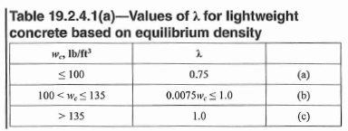 Table 2: Light Weight Concrete Factor as a Function of Density
20.2.2.4(a) - Maximum allowed grade of steel reinforcement. Use GR 60 bars as a minimum, GR 80 and GR 100 bars are mostly for seismic applications.
19.2.1.1 - Minimum allowed f’c. Generally advised to stay above 4 ksi. There is no maximum for f’c.
1.1 Design Assumptions
21.2.2.1 - Yield strain of reinforcement is calculated as follows. Note it is not always 0.002. Values differ for higher grade bars.
\[\epsilon_{ty} = \frac{f_y}{E_s} \tag 4\]22.2.2.1 - Maximum compressive strain is empirically determined to be around 0.003 to 0.004 but can go up to 0.008 in some special cases. The canadian code, for example, opts to use a slightly higher value of 0.0035
\[\epsilon_{cu} = 0.003 \tag 5\]22.2.2.3 - Stress distribution in concrete can be represented by a rectangular, parabolic, trapezoid stress block as long as it is in agreement with tests. Actual stress distribution is very complex.
22.2.2.4.1 - The rectangular stress block is characterized by 0.85f’c psi over a depth of “a” as shown in the figure below. “a” is a percentage of neutral axis depth “c”. \(\beta_1\) is empirically derived.
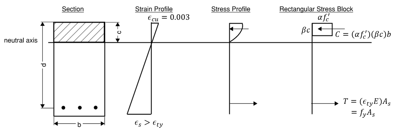 Figure 1: Rectangular Stress Block
\(\beta_1\) is equal to 0.85 for 4 ksi concrete, and decreases linearly by 0.05 per 1 ksi increase up to 0.65 for 8 ksi concrete.
\[\beta_1 = \left\{ \begin{array}\\ 0.85 & \mbox{if } \ f'_c \leq 4 \; ksi \\ 0.85-\frac{0.05(f'_c-4000)}{1000} & \mbox{if } \ 4\;ksi <f'_c < 8 \;ksi \\ 0.65 & \mbox{if } f'_c \geq 8 \;ksi \end{array} \right. \tag 7\] \[\beta_1 = max(0.65, min(0.85, 0.85-\frac{0.05(f'_c-4000)}{1000})) \tag 8\]1.2 Resistance Factors
21.2.1 - Strength reduction factor is different depending on element type and structural action. Refer to table 21.2.1 for full list.
- Moment/axial load, see 21.2.2: \(\phi=0.65 \;to\; 0.9\)
- Shear: \(\phi=0.75\), for earthquake-resisting elements, the factor may be reduced to \(\phi = 0.6\)
- Torsion: \(\phi=0.75\)
- Bearing: \(\phi=0.65\)
- Plain concrete (any loading): \(\phi=0.60\)
21.2.2 - Strength reduction factor for moment + axial combination depends on strain of tension reinforcement closest to tension face.
 Table 3: Resistance Factor for Axial + Moment
Higher resistance factor corresponds to higher ductility. Excessive deflection and cracking is good because it gives warning signs prior to failure. A net tensile strain of 0.005 is considered to provide sufficient ductility for most applications (Moment frames expect up to 0.0075). Net tensile strain under 0.002 is said to be compression-controlled and fails in a brittle manner.
Spiral ties confine the section better and thus we are able to get a higher resistance factor for compression-controlled to transition sections.
2.0 Section Strength
ACI 318 is exclusively based on LRFD (Load and Resistance Factored Design).
- Capacity is denoted by a \(\phi\) factor and subscript “n” (e.g. \(\phi P_n\))
- Demand is denoted by subscript “u”. (e.g. \(P_u\))
The basis of all design checks is to ensure a DCR (Demand-Capacity Ratio) of less than 1.0:
\[Capacity > Demand \tag 9\] \[\phi T_n > T_u \tag {10}\] \[DCR = \frac{demand}{capacity} = \frac{T_u}{\phi T_n} < 1.0 \tag {11}\]In a nutshell, without complicating things with probabilistic analysis. The difference between LRFD and ASD (allowable stress design) is that:
- LRFD: factor up loading (\(P_u\)), factor down capacity (\(\phi P_n\))
- ASD: loading is determined as is, factor down capacity (e.g. \(\frac{P}{\Omega}\))
2.1 Axial Capacity
22.4.2 - Axial capacity of a concrete section is calculated as 80% to 85% of the sum of compressive strength of concrete + reinforcement. The 20%-25% reduction is meant to account for accidental eccentricity.
\[P_n = 0.8P_o \tag {12}\] \[P_n = 0.8(0.85f'_c (A_g - A_{st})+f_yA_{st}) \tag {13}\]For spiral tied elements, we can use \(0.85P_o\) instead. Note the 0.85f’c is separate from 0.8Po percentage.
2.2 Flexural Capacity
Referring to Figure 1 above, moment capacity can be calculated as the internal force (T or C, doesn’t matter because they are equal), multiply by the distance between them; known as the internal lever arm and sometimes denoted as “jd”.
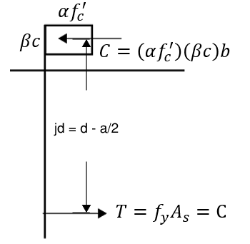
where:
\[T = f_yA_s\] \[a=\frac{f_yA_s}{0.85f'_cb}\]The full expression:
\[M_n = f_yA_s (d-\frac{f_yA_s}{2\alpha f'_c b}) \tag {15}\]To determine the correct resistance factor (\(\phi\)) to use, net tensile strain can be calculated with similar triangles. Then refer to Table 21.2.2.
\[\epsilon_s = \frac{d-c}{c} \epsilon_{cu} \tag {16}\]Approximate Solutions
Here is a life-changing trick! A very common, and scarily accurate back-of-envelope equation is often used for preliminary design. This is done by assuming an internal lever arm (say 0.9d)
\[\phi M_n = M_u = \phi f_y A_s (jd)\tag {17}\] \[M_u = \frac{(0.9)(60)A_s(0.9)d}{12} \tag {18}\] \[A_s = \frac{M_u}{4.05d} \tag {19}\]For example, say we have a 16”x30” beam experiencing 150 kip.ft of moment. Assume depth of 28 inches. We can literally calculate how many bars are required in our heads. 150/(4.05*28) = 1.32 square inch of steel area => (3) #6 bars.
To verify, if we calculate the moment capacity with (3) #6 bars rigorously, we get 162.7 kip.ft. Magic! We didn’t even need to know the concrete strength…
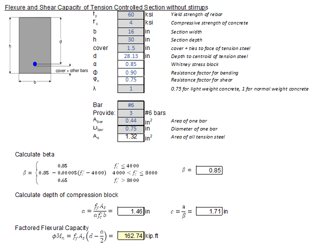
This approximate equation is predicated on the fact that \(T\) is easy to calculate, but the depth of neutral axis is trickier. Nevertheless, it is pretty much always in the range of 80% to 95% of depth “d”. Here is a list of recommended internal lever arm ratio “jd” :
- \(j = 0.75\) near compression failure
- \(j = 0.95\) near minimum steel
- Use 0.9 for slabs and light beams, 0.85 for heavier beams
Couple of notes on the state of practice for concrete design:
- Compression bars are rarely considered. Adding compression steel will always increase capacity and ductility. Therefore it is conservative to just assume singly-reinforced section
- T-beams are always sized such that the neutral axis stays above the web for simplicity. This is usually very easy to achieve. Alternatively, effective flanges are ignored all together because added compression area will only ever increase capacity.
- For multiple layers of tension bars, “jd” is calculated with respect to centroid of those bars. However, \(\phi\) factor is still based on the outermost bar.
Flexure + Axial Interaction
Combined P+M action requires the use of interaction diagrams as shown below. We will discuss the creation of interaction diagrams in another article. P+M points within the onion-shaped surface is OK. Outside the surface is no good. See this SkyCiv article for more information.
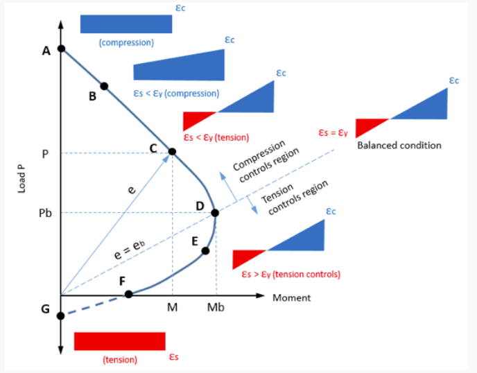
Two key observations:
- Moment capacity increases in compression (up until a very high axial demand). Typically, beams with a small amount of axial load is actually good (it’s like pre-stressing)
- Rather than producing an entire interaction diagram for T+M, notice the linear relationship between (dashed line in the figure above)! Therefore, Moment + Tension interaction can be approximated very accurately:
2.3 One-Way Shear Capacity
There were some drastic change to the shear capacity equation in ACI 318-19 compared to ACI 318-14. The equation now considers a “size effect” as well as the effect longitudinal reinforcement ratio has on shear capacity. No longer can we use the simple \(2\sqrt{f'_c}\) unless a minimum amount of transverse ties are provided.
- Doubling the section depth does NOT double the shear capacity. New size factor.
- More heavily reinforced section will have higher shear capacity
22.5.1.1 - Shear capacity of a section comes from concrete and transverse ties.
\[V_n = V_c + V_s \tag {20}\]22.5.5.1 - Shear capacity contribution from concrete
- if a nominal amount of ties \(A_{v,min}\) are provided, can use the old \(2\sqrt{f'_c}\) equation
- \(\rho_w\) is calculated with steel within the bottom 1/3 of section height.
- \(\lambda\) is a factor for normal or light-weight concrete
- Size factor is calculated per 22.5.5.1.3.
- \(A_{v,min}\) is calculated per 9.6.3.3. The first equation governs for any \(f'_c\) above 4500 psi. \(A_v\) is calculated as all shear reinforcement within spacing “s”
- If the section is under compression or tension, modify the allowable shear stress (within brackets above) by the following term. Shear capacity increases under compression, and decreases under tension. Applies to equation (21).
- Regardless of contribution from axial demand and longitudinal reinforcement, capacity offered by concrete cannot exceed \(5\sqrt{f'_c}\):
22.5.8.5.3 - Shear capacity contribution from steel is based on a truss analogy. The fraction \(d/s\) can be thought of as how many ties are within the 45 degree crack spaced at distance of “d”.
\[V_s =A_vf_{yt} \frac{d}{s} \tag {26}\]- Per 22.5.1.2, shear capacity provided by transverse ties cannot exceed \(8\sqrt{f'_c}\). Cannot infinitely increase shear capacity with steel. At some point diagonal compression failure occurs.
There are several other important design constraints to note:
-
22.5.2.1 - “d” does not need to be less than 0.8h. This applies when you have multiple layers of tension bar that extends up the depth.
-
22.5.3.1 - \(f'_c\) is capped at 10 ksi. Should not use higher due to lack of experiment data.
-
22.5.3.3 - \(f_y\) is capped at 60 ksi regardless of actual steel grade in order to avoid diagonal compression failure
22.5.1.10 - For elements resisting shear in two orthogonal directions, an interaction equation can be used. Alternatively, if shear DCR in any direction is less than 50%, can ignore this interaction.
\[\frac{v_{ux}}{\phi v_{nx}} + \frac{v_{uy}}{\phi v_{ny}} \leq 1.5 \tag {28}\]2.4 Punching Shear Capacity
Punching Shear Demand
R8.4.4.2.3 - Punching shear demand, also known as two-way shear demand is usually converted into stress by dividing factored shear demand (Vu) divide by the effective perimeter area. In addition, unbalanced moment from two-way slabs (such as edge or corner condition), tend to contribute a significant portion of shear stress and should not be omitted. Usually interior and edge columns have only unbalanced moment in one direction, corner columns have unbalanced moment about both directions.
\[v_u = \frac{V_u}{b_o d} + \frac{\gamma_v M_{scx} c}{J_x} + \frac{\gamma_v M_{scy} c}{J_y}\tag {29}\]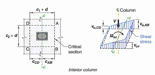 Figure 2: Two-Way Shear Stress With Unbalanced Moment Contribution
- The expression above is analogous to P/A + My/I
- c is distance from centroid of column to edge of critical perimeter in the direction of unbalanced moment
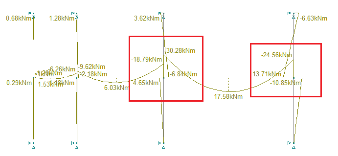 Figure 3: Unbalance Moment Arising From Unequal Span
- Unbalanced moment may arise from unequal span, or edge conditions. Refer to figure 3 above, notice how moment to the left and right of the highlighted supports is discontinuous, a certain amount is transferred to the columns. This unbalanced moment must be resolved either within the slab itself, or transfer to the column, which creates additional shear stress. The amount of unbalanced moment transferred to column is calculated per 8.4.4.2.2 and 8.4.2.2.2
- \(b_1\) is column dimension parallel to span under consideration, \(b_2\) is perpendicular.
- J is a section property analogous to polar moment of inertia. \(I_x\) and \(I_y\) is calculated from the perimeter area parallel to bending direction (\(b_1d^3/12\) and \(db_1^3/12\)). \(\sum Ad^2\) is calculated from perimeter area perpendicular to bending direction (\(2 \times (b_2d)(b_1)^2\))
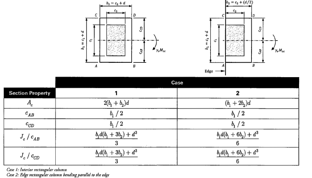
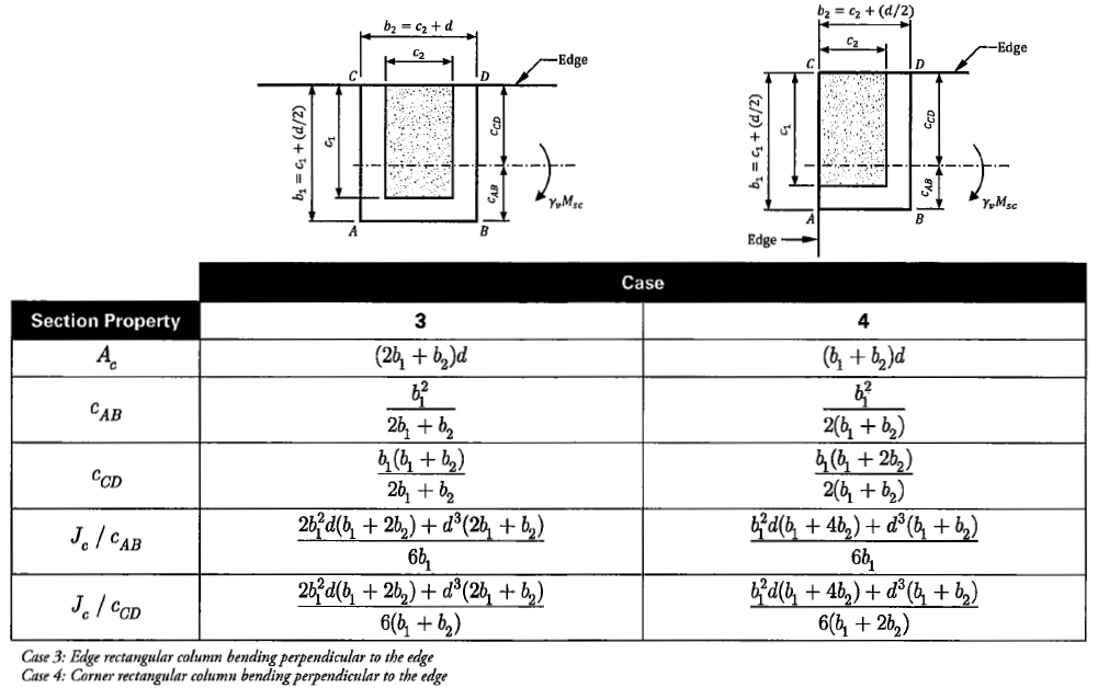 Figure 4: Equation to Calculate J (Source: CRSI)
For other shapes such as circular column, or trapezoidal section, refer to CRSI ACI 318-19 design guide.
Critical Section
22.6.4.1 - The effective perimeter area (\(b_od\)) is calculated based on an assumed 45 degree breakout cone. However, for simplicity, it can be taken as d/2 away from edge of column. Refer to the figure below for some different conditions.
22.6.4.2 - If the section is reinforced with stud rails or stirrups, then another critical section must be evaluated just outside of the reinforced perimeter. This section will have a reduced capacity.
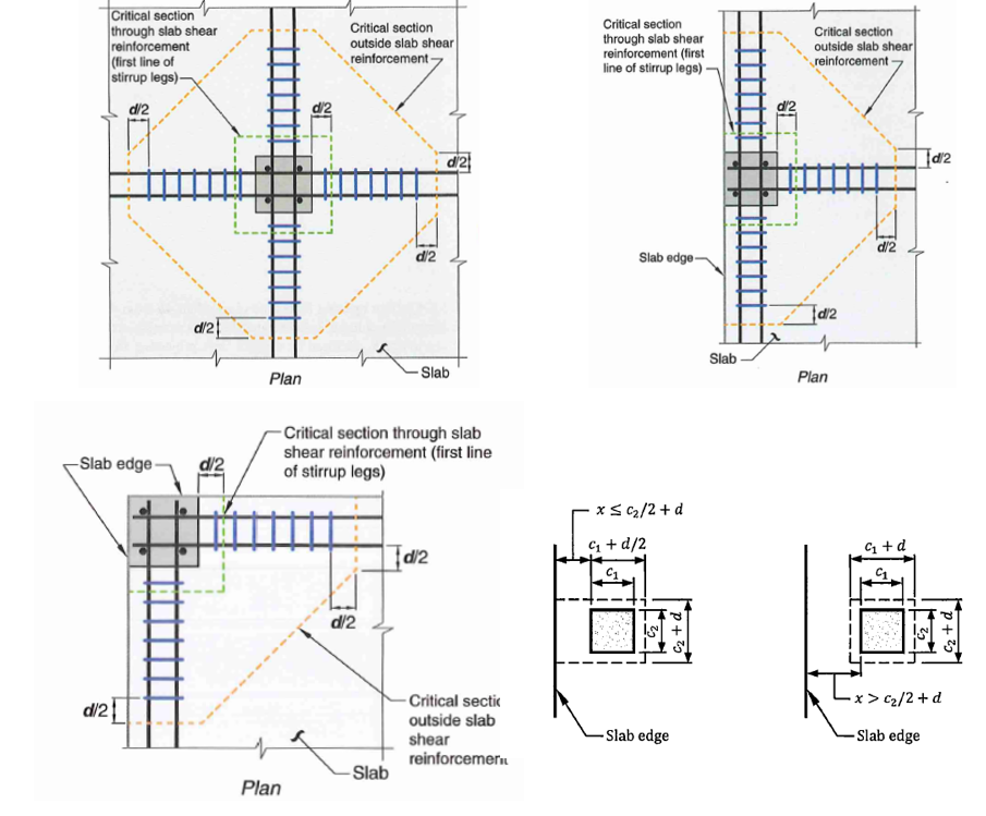 Figure 5: Critical Section for Punching Shear
- depth is taken as the average depth in the two orthogonal bar layer. It need not be less than 0.8h per 22.6.2.1 and 22.6.2.2
- slab openings within 4h of column must be considered as shown in the figure below.
 Figure 6: Openings near Critical Section
Punching Shear Capacity of Unreinforced Concrete
Originally, the allowable shear stress for two-way shear is taken simply as \(4\sqrt{f'_c}\). However, this was found to be unconservative in certain situations. Clause 22.6.5.2 defines the punching shear capacity as the minimum of three equations.
\[v_{c1} = (4) \lambda_s \lambda \sqrt{f'_c} \tag {32}\] \[v_{c2} =(2 + 4/\beta) \lambda_s \lambda \sqrt{f'_c} \tag {33}\] \[v_{c3} =(2 + \frac{\alpha_sd}{b_o}) \lambda_s \lambda \sqrt{f'_c} \tag {34}\]- Equation (32) is for your typical condition, equation (33) governs for very high aspect ratio rectangular columns, equation (34) is where column perimeter is too large
- \(\lambda_s\) is the size factor mentioned in one-way shear
- \(\beta\) is the ratio of long to short size of column dimension
- \(\alpha_s\) is given in 22.6.5.3 and is equal to 40 for interior column, 30 for edge column, 20 for corner column. Essentially Number of sides under shear multiply by 10
Generally, we would want to keep punching shear DCR to well within 0.8 due to the brittle nature of failure. There are several options we have for increasing the capacity:
- increase slab depth, or add drop panel or drop band to increase “d”
- add column capital to increase “bo”
- add stud rails or stirrups which creates two failure cones that must be evaluated
Punching Shear Capacity of Concrete Reinforced With Stirrups
22.6.7.1 - In order for stirrups to be fully anchored and developed, there are some depth requirements. Slab depth to rebar “d” must be at least 6” or 16 times the bar diameter. Therefore, if we were using #4 stirrups with 0.75” cover, the slab has to be at least 8.75 inches for us to utilize stirrups in resisting punching shear.
22.6.6.1 - capacity of stirrups can only be initiated past a certain degree of inclined cracking. Therefore, punching shear capacity of concrete is reduced by half.
\[v_c = 2 \lambda_s \lambda \sqrt{f'_c} \tag {35}\]22.6.6.2 - size factor \(\lambda_s\) may be taken as 1.0 if \(A_v /s \geq 2\sqrt{f'_c} b_o / f_{yt}\)
22.6.7.2 - punching shear capacity provided by stirrup is calculated as:
\[v_s = \frac{A_v f_{yt}}{b_o s} \tag {36}\]- ”s” is the spacing of stirrups placed orthogonally from column
- “Av” is the total area of stirrups along a “peripheral line”, which is based on how many ties are along a perimeter. For example, if there are 2 legs of #4 ties per side, then in total Av = 8 * 0.2 = 1.6
- Capacity provided by steel can not exceed \(\phi 6 \sqrt{f'_c}\) per 22.6.6.3
- detailing of stirrups are subject to requirements of section 8.7.6
Lastly, the critical section outside of the reinforced perimeter must also be checked with equation (35).
Punching Shear Capacity of Concrete Reinforced With Stud Rails
Contrary to stirrups, there are no slab depth requirements for using stud rails. Most likely due to the better anchoring mechanism formed by the headed studs.
22.6.6.1 - similar to stirrups, concrete capacity must be reduced in the presence of shear studs. Capacity is equal to the minimum of the three equations below. Note the only change is reduction of \(4\sqrt{f'_c}\) to \(3\sqrt{f'_c}\)
\[v_{c1} = (3) \lambda_s \lambda \sqrt{f'_c} \tag {37}\] \[v_{c2} =(2 + 4/\beta) \lambda_s \lambda \sqrt{f'_c} \tag {38}\] \[v_{c3} =(2 + \frac{\alpha_sd}{b_o}) \lambda_s \lambda \sqrt{f'_c} \tag {39}\]Important Note: based on research by Professor Parra-Montesinos at the University of Michigan, Ann Arbor. There is evidence of premature failure due to cracks emanating from column corners for orthogonally placed stud rails (article here). It is recommended to place shear studs in a radial manner. Furthermore, a ESR report was published (ESR-2494 and ESR 2708) that recommends reducing the existing code capacity equations by half to \(1.5 \sqrt{f'_c}\). Therefore, until more research is done, it is recommended to reduce the above equations by half.
22.6.8.2 - punching shear capacity provided by stud rails:
\[v_s = \frac{A_v f_{yt}}{b_o s} \tag {40}\]- Capacity provided by stud rails can not exceed \(\phi 8 \sqrt{f'_c}\) per 22.6.6.3
- Contrary to stirrups, the requirement \(A_v /s \geq 2\sqrt{f'_c} b_o / f_{yt}\) must be satisfied per 22.6.8.3.
- detailing of stud rails subject to requirements of section 8.7.7
Lastly, the critical section outside of the reinforced perimeter must also be checked with the capacity below:
\[v_c = 2 \lambda_s \lambda \sqrt{f'_c} \tag {41}\]Finally, similar to one-way shear, there are some material property requirements. f’c is limited to 100 ksi per 22.6.3.1, fyt is limited to 60 ksi per 22.6.3.2. Material upper bound strength intended to prevent excessive cracking. Also because of lack of test data.
2.5 Shear Friction
The theory of shear friction is very empirical and is based on an assumption of a clamping force provided by steel reinforcement perpendicular to shear crack. As a shear crack forms, aggregate interlock prevents a clean separation. The separating action engages the steel reinforcement. Because the structural action is actually tension, the doweling bars must be fully developed on both ends of the crack surface per 22.9.5.1.
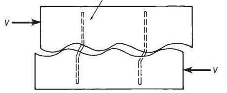
22.9.1.1 - Despite adequate one-way shear capacity, a member may still develop unfavorable shear cracks at odd angles. Another possibility is cracks forming at construction/cold joints or interface between dissimilar materials.
22.9.4.2 - shear friction capacity is calculated as shown. Note fy is limited to 60 ksi per 22.9.1.3 regardless of actual steel grade due to lack of test data.
\[V_{vf} = \mu A_{vf} f_y + N_c \tag {42}\]- \(A_{vf}\) is the area of reinforcement crossing the shear plane
- \(N_c\) is a net permanent compression across the shear plane and is added to the shear friction capacity. It can be conservatively ignored.
- \(\mu\) is the coefficient of friction empirically determined to be the following:
- \(\mu = 1.4\) if failure plane must go through monolithic concrete such as through a shear-key
- \(\mu = 1.0\) if failure plane is cleaned and intentionally roughed to 1/4” amplitude
- \(\mu = 0.6\) for a concrete cold joint that is not roughened
- \(\mu = 0.7\) for concrete cast against structural steel
22.9.4.4 - shear friction capacity is capped to an upper-bound value based on experimental studies. The ceiling is calculated as the minimum of three equations for monolithic or roughed slip surface:
\[(0.2f'_c) A_c \tag {43}\] \[(480 + 0.08f'_c) A_c \tag {44}\] \[(1600f'_c) A_c \tag {45}\]Equation (44) will always govern for f’c between 4000 psi and 8000 psi.
For un-roughened surface or concrete against structural steel, upper bounds is the minimum of two equations
\[(0.2f'_c) A_c \tag {46}\] \[(800f'_c) A_c \tag {47}\]Equation (47) will always govern for f’c between 4000 psi and 8000 psi.
22.9.4.6 - For permanent net tension, additional reinforcement area must be added to resist the net tension in addition to the bars for shear friction. This applies to flexural tension as well. In practice, flexural steel is often designed separately from shear friction dowels.
R22.9.4.6 - Moment acting on the slip surface is often ignored because net axial load is zero (shear friction capacity increases in compression zone, and decreases in tension zone). Ideally shear friction dowels should be placed uniformly to minimize crack width.
22.9.4.3 - shear friction dowels can also be placed at an incline angle (\(\alpha\)) but this is extremely rare.
\[V_{vf} = (\mu sin \alpha + cos \alpha) A_{vf} f_y + N_c \tag {48}\]2.6 Torsion
Types of Torsion
Torsion is in general under-discussed in structural design because it is one of the weakest and least stiff load path. Furthermore, aside from tube sections, torsion is usually non-uniform and creates an additional warping stress which is very complex to characterize. Therefore, engineers usually create another load path to external loads causing torsion. Nevertheless, sometimes torsion is unavoidable due to design constraints.
22.7.3 - The first step is to determine what type of torsion is occurring. There are two types:
- Equilibrium torsion - stability of structure is dependent on torsion capacity
- Compatibility torsion - torsion moment is non-critical because redistribution of force is possible.
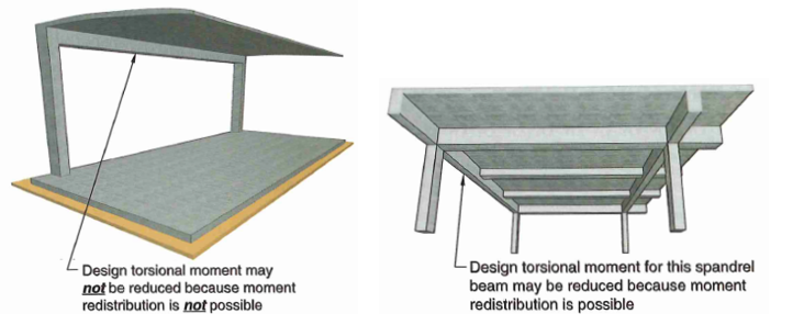 Figure 7: Two Types of Torsion
Redistribution must be accounted for in analysis. For example, if redistribution occurs in the spandrel beams in figure 7 above, then the slab must be designed for increased positive bending. Technically only 20% of moment redistribution is allowed per 6.6.5.3, but this is due to lack of test data rather than an actual physical observation. In practice, this clause is often disregarded or at least not explicitly calculated. For example, it is common to design slab edge connection to retaining wall as pinned. Concrete structures are highly indeterminate which means multiple load paths exist, allowing such redistribution to occur.
Torsion Demand
22.7.4.1 - Next we need to determine whether or not the torsion demand is high enough to warrant consideration at all. The threshold torsion is calculated as follows for non-prestressed solid cross section.
\[T_{th} = \lambda \sqrt{f'_c} (\frac{A_{cp}^2}{p_{cp}}) \sqrt{1+ \frac{N_u}{4A_g \lambda \sqrt{f'_c}}} \tag {49}\]- \(N_u\) is positive for compression, negative for tension
- \(A_{cp}, p_{cp}\) is the gross area and perimeter
From here, there are three possibilities:
- \(T_u\) from analysis is less than threshold torsion, no need to consider torsion at all
- Compatibility torsion \(T_u\) from analysis is greater than threshold torsion, torsion demand is capped at cracking torsion per 22.7.3.2
- Equilibrium torsion \(T_u\) from analysis is greater than threshold torsion torsion demand is not capped. Design for \(T_u\).
Torsion Capacity
Torsion design in concrete is based on a space truss analogy where the core is essentially neglected. Torsion demand is resisted by three actions: diagonal compression strut, vertical shear, and horizontal tension. What makes torsion calculation tedious is the fact that it is not decoupled and must be considered in tandem with shear and flexure. Torsion demand seldom exist in isolation.
 Figure 8: Torsion Action - 3D Truss Analogy
22.7.7.1 - To prevent excessive cracking and diagonal crushing of concrete. The following limit is set for solid sections and should be check first. Increase section size if not workable.
\[\sqrt{(\frac{V_u}{b_w d})^2 + (\frac{T_u p_h}{1.7A_{oh}^2})^2} \leq \phi (\frac{V_c}{b_w d}+ 8 \sqrt{f'_c}) \tag {51}\]- \(A_{oh}, p_{h}\) is the area and perimeter enclosed by stirrups or ties
22.7.6.1 - Torsion capacity is calculated as the minimum of the following. The first expression is related to transverse steel, the second expression is related to longitudinal steel.
\[T_n = \frac{2A_o A_t f_{yt}}{s} cot \theta \tag {52}\] \[T_n = \frac{2A_o A_l f_{y}}{p_h} tan \theta \tag {53}\]- \(A_{o} = 0.85 A_{oh}\) per 22.7.6.1.1
- \(\theta = 45\) for non-prestressed members per 22.7.6.1.2
The above equations may be suitable for analysis of existing members. However, this is almost never used for design because of how intertwined torsion is to flexure and shear. Instead, use the procedure below for design.
1.) Determine transverse steel ratio required for shear:
\[\frac{A_v}{s} = \frac{V_u - \phi V_c}{\phi d f_{yt}} \tag {54}\]2.) Determine transverse steel ratio required for torsion:
\[\frac{A_v}{s} = \frac{T_u}{\phi 2 cot \theta A_o f_{yt}} \tag {54}\]3.) Combine the effect of shear and torsion:
\[(\frac{A_v}{s})_{total} = (\frac{A_v}{s})_{torsion} + (\frac{A_v}{N_{leg}\times s})_{shear} \tag {55}\]4.) Given you have selected a stirrup size, the required spacing is calculated as:
\[s_{req} = \frac{A_{bar}}{(\frac{A_v}{s})_{total}} \tag {56}\]Lastly, all four sides of a member must have longitudinal reinforcement for torsion. The amount of additional longitudinal steel is calculated as:
\[A_l = (\frac{A_v}{s})_{torsion} \times p_h (\frac{f_{yt}}{f_y}) cot^2(\phi) \tag {57}\]A minimum steel area is specified in 9.6.4.3 as the less or two equations:
\[A_{lmin} = \frac{5\sqrt{f'_c}A_{cp}}{f_y} - (\frac{A_t}{s})p_h \frac{f_{yt}}{f_y} \tag {58}\] \[A_{lmin} = \frac{5\sqrt{f'_c}A_{cp}}{f_y} - (\frac{25b_w}{f_{yt}})p_h \frac{f_{yt}}{f_y}\tag {59}\]Divide the steel area above by 4 to spread into four faces of the section. The top and bottom face usually have enough steel, but it is necessary to ensure the side faces have at least \(A_l/4\) as well. To check if flexural steel is enough:
\[A_{s,flexure} = \frac{Mu}{\phi f_y jd} \tag {60}\]if \(A_{s,flexure} + A_l/4 < A_{s,provided}\), then we are okay. Otherwise increase longitudinal steel.
2.7 Bearing
Bearing most commonly occurs when a structural steel member “bears” onto the concrete such as at a steel column base plate. It could also occur between two concrete member such as at a pre-cast beam support, or a shear keys. Typically, concrete bearing failure occurs at around 0.85f’c, which is why you will see the 0.85 coefficient everywhere. If the support area is must larger than the load area, the surrounding concrete provides a confinement effect which results in up to double the bearing capacity.
22.8.3.1 - Design bearing strength is calculated as follows:
\[B_n = \gamma 0.85f'_c \tag {61}\]- \(\gamma\) is a factor based on degree of confinement provided by surrounding concrete
- if loaded area is equal to support area, then \(\gamma = 1\)
- if supporting area is wider on all sides, then use the following equation:
- \(A_1\) is the loaded area
- \(A_2\) is the projected area based on a 2H:1V line as shown in the figure below.
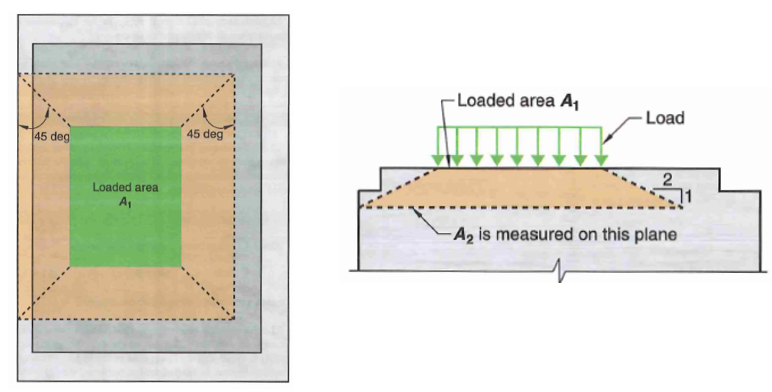 Figure 9: Bearing Area Definition
3.0 Reinforcement Detailing
3.1 Cover and Spacing
25.2.1 - minimum rebar spacing should be the maximum of 1 in, one bar diameter, or (4/3) the diameter of aggregates. This is to ensure concrete can move into spaces between bars. However, practically speaking you should never have bars spaced less than 3 in.
20.5.1.3.1 - minimum cover to face of reinforcing steel is specified as follows:
- 3” = Concrete cast permanently in contact with earth (retaining wall, footing, mat, piles, etc)
- 2” = Concrete that is exposed to weather (#6 to #11)
- 1.5” = Concrete that is exposed to weather (#3 to #5)
- 1.5” = beams, columns, pedestals with interior condition
- 0.75” = Slab, joists, walls with interior condition (#3 to #11)
3.2 Development Length - Method 1
The first method of calculating development length is a simplified version of method 2 (next section) that preselects some typical \(c_b + K_r / d_b\) values. They are as follows. Regardless of equations used, development length \(l_d\) shall not be less than 12 inches per 25.4.2.1.
- clear spacing at least 2db, clear cover at least 1db (this is most used for typical details):
- Other cases:
- The various modification factors are given in Table 25.4.2.5:
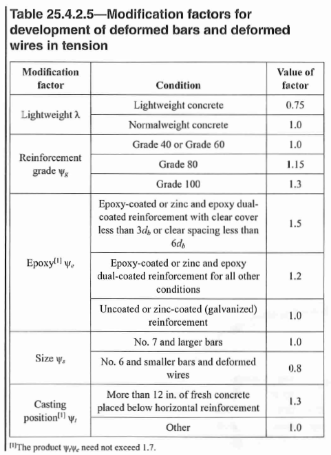 Figure 10: Development Length (ld) Factors
3.3 Development Length - Method 2
25.4.2.4 - Alternatively, you can calculate development length more accurately and a lot less conservatively with the equation below:
\[l_d = \frac{3 f_y \Psi_t \Psi_e \Psi_g \Psi_s}{40 \lambda \sqrt{f'_c} \frac{c_b + K_{tr}}{d_b}} d_b > 12in \tag {65}\]- \(c_b\) is the lesser of cover to bar or half of center to center bar spacing.
- \(K_tr\) is the confinement term that must not exceed 2.5:
- “n” is the number of bars developed in the plane of splitting, “Atr” is the total area of transverse reinforcement that crosses the splitting plane, “s” is the spacing of those transverse bars. As a design simplification, it is permitted to just take \(K_{tr} = 0\)
3.4 Development Length - Hooks
25.4.3.1 - development length of hook bars is calculated as follows, but shall not be less than 6” or \(8d_b\)
\[l_{dh} = \frac{f_y \Psi_e \Psi_r \Psi_o \Psi_c}{55 \lambda \sqrt{f'_c}} d_b^{1.5} > max(6in,8d_b) \tag {67}\]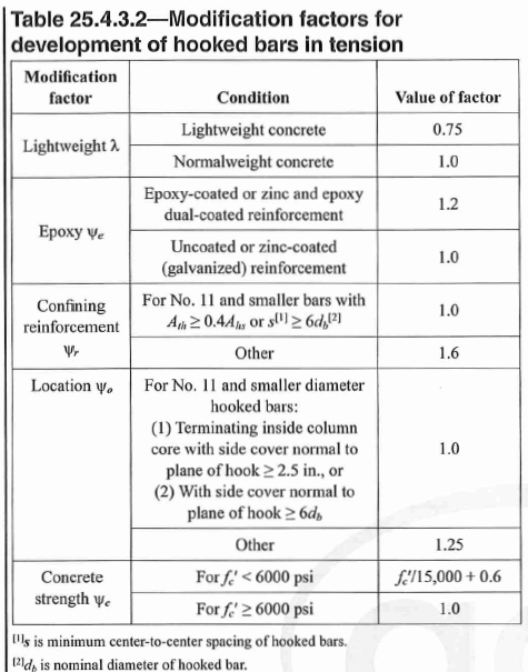 Figure 10: Hook Development Length (ldh) Factors
3.5 Development Length - Headed Bars
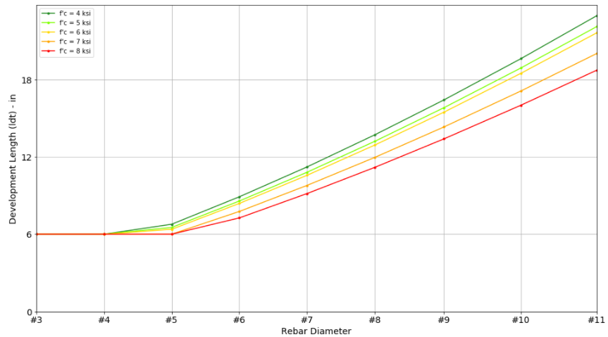
25.4.4.2 - development length of headed bars (also known as T-heads) is calculated as follows, but shall not be less than 6” or \(8d_b\)
\[l_{dh} = \frac{f_y \Psi_e \Psi_p \Psi_o \Psi_c}{75 \lambda \sqrt{f'_c}} d_b^{1.5} > max(6in,8d_b) \tag {68}\]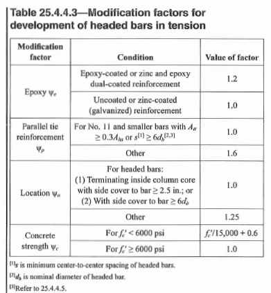 Figure 11: Headed Bars Development Length (ldt) Factors
25.4.4.1 - furthermore, headed bars cannot be used in light-weight concrete due to lack of data.
3.6 Tension Lap Splice
For simplicity, lap splice length is typically taken as \(1.3l_d\). A reduction may be permitted for specially detailed stagger splice. See 25.5.2.1.
3.7 Compression Development Length
25.4.9.1 - compression development length (\(l_{dc}\)) is calculated as follows:
\[l_{dh} = \frac{f_y \Psi_r}{50 \lambda \sqrt{f'_c}} d_b > max(8in,0.0003f_y\Psi_r d_b) \tag {70}\]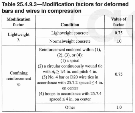 Figure 12: Compression Development Length (ldc) Factors
Development Length Design Table
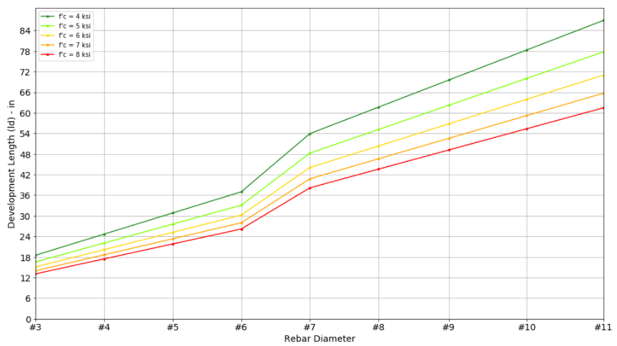
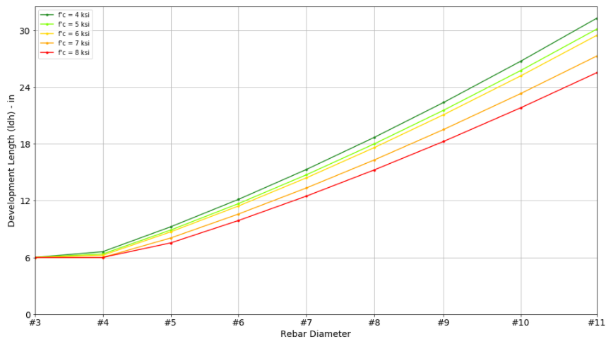
Here are some useful design charts assuming some of the most common design properties:
- Clear spacing at least 2db, clear cover at least 1db
- Bottom bars without at least 12 in of fresh concrete placed below
- non-epoxy rebar
- normal weight concrete
- fy = 60 ksi
- hooks and headed bars are adequately confined/spaced (spacing greater than 6db). Wr = 1.0
- hooks and headed bars has enough side cover (side cover more than 6db). Wo = 1.0
Multiply the charted value by the following modification factors if appropriate. However, Ld must not be less than 12” and Ldt/Ldh must not be less than 6”.
- multiply ld, ldh, and ldt by 1.33 if using light-weight concrete
- multiply ld by 1.53 for GR 80 bars
- multiply ld by 1.33 if top bar with more than 12” of concrete placed below
- multiply ldt and ldh by 1.6 is spacing exceeds 6db
- multiply ldt and ldh by 1.25 if side cover exceeds 6db
Straight Bar Development Length(ld)
Hook Development Length (ldh)
Headed Bar Development Length (ldt)
Comments