Element Stiffness Matrix With Shear Deformation
1. Deriving Stiffness Matrix by Inverting Flexibility Matrix
There are several ways to derive the stiffness matrix of a beam element. One of these methods involve inverting a flexibility matrix. This method fairly easy to understandable and doesn’t involve too much higher level mathematics. For more information, refer to chapter 4 of the MASTAN textbook.
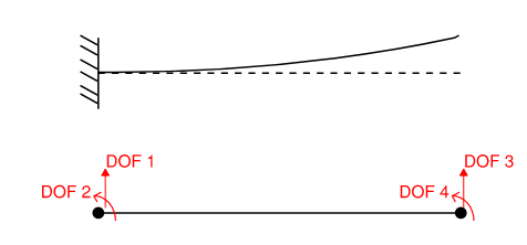
First, we need to derive the flexibility coefficients of this cantilever beam structure. We may also use a simply-supported beam. The main point is to impose boundary conditions onto two degree of freedoms (DOF) such that the structure is stable. This is required in order to obtain flexibility coefficients.

Recall that flexibility coefficients dij are simply displacements and can be defined as displacement at DOF i due to unit force at DOF j. For example, d23 refers to displacement in the vertical direction due to a unit couple at DOF 3. These displacement coefficients can be computed using any methods taught in structural analysis courses. The resulting matrix {d} is:
\[[d] = \begin{bmatrix} \frac{L^3}{3EI} & \frac{L^2}{2EI} \\ \frac{L^2}{2EI} & \frac{L}{EI} \\ \end{bmatrix}\\\]What happens if we invert this flexibility matrix? Do we get the stiffness matrix? Not quite but almost… First of all, the stiffness matrix should be a 4x4 matrix. We need to somehow obtain information from the two degrees of freedoms that we fixed.
\[[d]^{-1} = \begin{bmatrix} \frac{12EI}{L^3} & \frac{-6EI}{L^2} \\ \frac{-6EI}{L^2} & \frac{EI}{L} \\ \end{bmatrix}\\\] \[\begin{bmatrix} F_3 \\ M_4 \end{bmatrix}\\ = \begin{bmatrix} \frac{12EI}{L^3} & \frac{-6EI}{L^2} \\ \frac{-6EI}{L^2} & \frac{EI}{L} \\ \end{bmatrix}\\ \begin{bmatrix} \Delta_3 \\ \theta_4 \end{bmatrix}\\\]
We need a way to transform a 2x2 flexibility matrix into a 4x4 stiffness matrix. The most straight forward method is to expand the matrix above into two equations. Along with equations of equilibrium and symmetry, we can derive all of the stiffness coefficients with a bit of algebra. Note that stiffness coefficients kij is defined as force at DOF i due to unit displacement at DOF j, all other DOF fixed, each column of the stiffness matrix is in essence a equilibrium condition.
For example, the third column of the stiffness matrix corresponds to the following set of displacement and rotation:
\[\{\Delta_1=0, \theta_2=0, \Delta_3=1, \theta_4=0 \}\] \[\begin{bmatrix} k_{13} \\ k_{23} \\ k_{33} \\ k_{43} \\ \end{bmatrix}\\ = \begin{bmatrix} k_{11} & k_{12} & k_{13} & k_{14} \\ k_{21} & k_{22} & k_{23} & k_{24} \\ k_{31} & k_{32} & k_{33} & k_{34} \\ k_{41} & k_{42} & k_{43} & k_{44} \end{bmatrix}\\ \begin{bmatrix} 0\\ 0\\ 1\\ 0\\ \end{bmatrix}\\\]From our inverted flexibility matrix, we have the following:
\[F_3=k_{33} = \frac{12EI}{L^3} \;,\; M_4 =k_{43}= \frac{-6EI}{L^2}\]From equilibrium, we can derive the other two stiffness coefficient:
\[F_1 = k_{13}=-F_3 = \frac{-12EI}{L^3}\] \[M_2 = k_{23}=-F_3L-M_3 = \frac{-12EI}{L^3}(L) - \frac{-6EI}{L^2} = \frac{-6EI}{L^2}\]Repeat for the other 4 columns, taking advantage of symmetry and the stiffness terms we’ve already derived. Another more convenient way to obtain our stiffness matrix is to use an equilibrium matrix relating V and M to the element’s internal forces. This is known as a “contragredient relationship”.
\[\begin{bmatrix} F_2 \\ M_3 \\ F_5 \\ M_6 \end{bmatrix}\\ = \begin{bmatrix} -1 & 0 \\ -L & -1 \\ 1 & 0 \\ 0 & 1 \end{bmatrix}\\ \begin{bmatrix} V \\ M \\ \end{bmatrix}\\\] \[[T]^T= \begin{bmatrix} -1 & 0 \\ -L & -1 \\ 1 & 0 \\ 0 & 1 \end{bmatrix}\\\] \[[k] = [T]^T[d]^{-1}[T]\]Carrying out the matrix multiplication above gets us the element stiffness matrix!
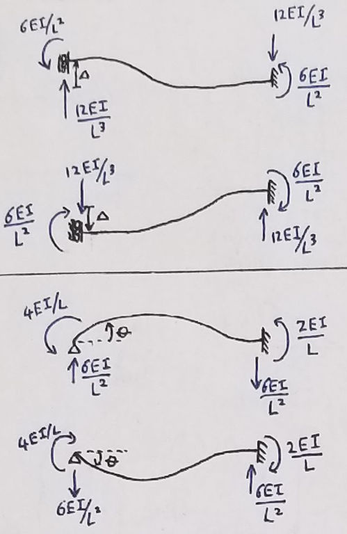
\[[k] = \begin{bmatrix} \frac{12EI}{L^3} & \frac{6EI}{L^2} & \frac{-12EI}{L^3} & \frac{6EI}{L^2} \\ \frac{6EI}{L^2} & \frac{4EI}{L} & \frac{-6EI}{L^2} & \frac{2EI}{L}\\ \frac{-12EI}{L^3} & \frac{-6EI}{L^2} & \frac{12EI}{L^3} & \frac{-6EI}{L^2}\\ \frac{6EI}{L^2} & \frac{2EI}{L} & \frac{-6EI}{L^2} & \frac{4EI}{L} \end{bmatrix}\\\]Here is a useful figure that shows all the relevant stiffness coefficients within the above stiffness matrix.

Here is a snippet of python code to illustrate what’s explained above:
# Import
import sympy as sy
import numpy as np
A,I,L,J,G,E,x= sy.symbols('A,I,L,J,G,E,x')

# calculate flexibility coefficient with principle of virtual works
d33 = sy.integrate((L-x)**2/E/I,[x,0,L])
d44 = sy.integrate(1/E/I,[x,0,L])
d34 = sy.integrate((L-x)/E/I,[x,0,L])
d43 = d34 #maxwell betti reciprocal theorem

d_noshear = sy.Matrix([
    [d33,d34],
    [d43,d44]])

T=sy.Matrix([
    [-1,-L,1,0],
    [0,-1,0,1]])

K_noshear = T.transpose() * d_noshear.inv() * T

print("Stiffness matrix without shear deformation")
K_noshear
2. Inclusion of Shear Deformation
To include shear deformation into our stiffness matrix, we will follow the same procedure as above. The only difference is that we need to include shear deformation into our flexibility coefficients. Recall that principle of virtual works allows this by including another integration term (\(\Delta = \int{\frac{mM}{EI} dx} + \int{\frac{vV}{GA} dx}\)).
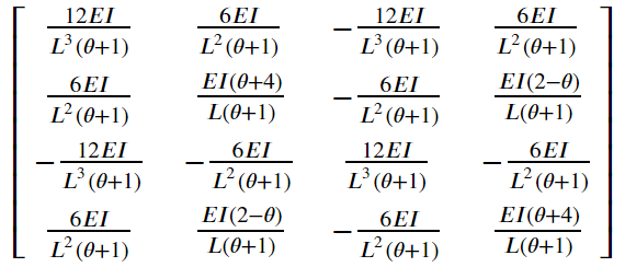
\[[d] = \begin{bmatrix} \frac{L^3}{3EI} + \frac{L}{A_vG} & \frac{L^2}{2EI} \\ \frac{L^2}{2EI} & \frac{L}{EI} \\ \end{bmatrix}\\\] \[[k] = [T]^T[d]^{-1}[T]\]Therefore, the 4x4 beam element stiffness matrix with shear deformation is as follows. The resulting stiffness matrix is sometimes referred to as Timoshenko beam element. Note “A” refers to effective shear area which differs depending on section geometry.

Alternatively, the matrix is expressed as the following (From Professor Henri Gavin’s CEE 421L course notes):

where:
\[\theta = \frac{12EI}{GAL^2}\]Here is the code snippet for calculation described above:
# Import
import sympy as sy
import numpy as np
A,I,L,J,G,E,x= sy.symbols('A,I,L,J,G,E,x')

# calculate flexibility coefficient with principle of virtual works
d33 = sy.integrate((L-x)**2/E/I,[x,0,L]) + sy.integrate(1/G/A,[x,0,L])
d44 = sy.integrate(1/E/I,[x,0,L])
d34 = sy.integrate((L-x)/E/I,[x,0,L])
d43 = d34

d_shear = sy.Matrix([
    [d33,d34],
    [d43,d44]])

T=sy.Matrix([
    [-1,-L,1,0],
    [0,-1,0,1]])

K_shear = T.transpose() * d_shear.inv() * T

print("Stiffness matrix with shear deformation")
sy.simplify(K_shear)

# Do a quick comparison with matrix equation found online
theta = 12*E*I/G/A/L/L
k_shear_alternative = sy.Matrix([
    [12*E*I/L**3/(1+theta),6*E*I/L/L/(1+theta),-12*E*I/L**3/(1+theta),6*E*I/L/L/(1+theta)],
    [6*E*I/L/L/(1+theta),(4+theta)*E*I/L/(1+theta),-6*E*I/L/L/(1+theta),(2-theta)*E*I/L/(1+theta)],
    [-12*E*I/L**3/(1+theta),-6*E*I/L/L/(1+theta),12*E*I/L**3/(1+theta),-6*E*I/L/L/(1+theta)],
    [6*E*I/L/L/(1+theta),(2-theta)*E*I/L/(1+theta),-6*E*I/L/L/(1+theta),(4+theta)*E*I/L/(1+theta)]
])

print("Another representation")
k_shear_alternative

print("subtrat each other to chcek if equal")
sy.simplify(K_shear - k_shear_alternative)
3. Comparing Stiffnesses
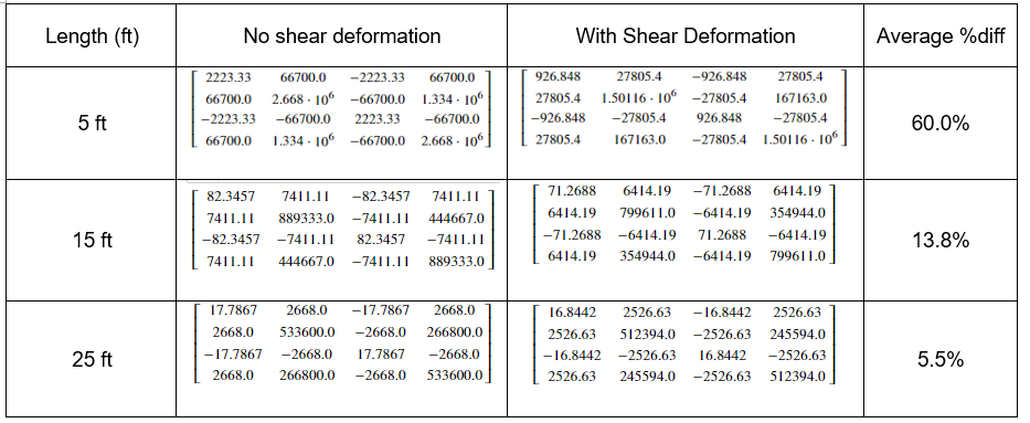
The inclusion of shear deformation should theoretically soften a structure (i.e. reduce the stiffness), but by how much? Let’s do some comparisons with a W14x120 section.
 Figure 1: Stiffness Matrix Comparison
As expected, shear deformation dominates for short span elements. Here is the python code snippet if you want to try for yourself:
# Imports
import sympy as sy
import numpy as np
A,I,L,J,G,E,x= sy.symbols('A,I,L,J,G,E,x')

# stiffness without shear deformation
d33 = sy.integrate((L-x)**2/E/I,[x,0,L])
d44 = sy.integrate(1/E/I,[x,0,L])
d34 = sy.integrate((L-x)/E/I,[x,0,L])
d43 = d34 #maxwell betti reciprocal theorem
d_noshear = sy.Matrix([
    [d33,d34],
    [d43,d44]])
T=sy.Matrix([
    [-1,-L,1,0],
    [0,-1,0,1]])
K_noshear = T.transpose() * d_noshear.inv() * T

# stiffness with shear deformation
d33 = sy.integrate((L-x)**2/E/I,[x,0,L]) + sy.integrate(1/G/A,[x,0,L])
d44 = sy.integrate(1/E/I,[x,0,L])
d34 = sy.integrate((L-x)/E/I,[x,0,L])
d43 = d34
d_shear = sy.Matrix([
    [d33,d34],
    [d43,d44]])
T=sy.Matrix([
    [-1,-L,1,0],
    [0,-1,0,1]])
K_shear = T.transpose() * d_shear.inv() * T

# define a function to get average difference
def percentagediff(A,B):
    diff_matrix=np.zeros([4,4])
    for i in range(4):
        for j in range(4):
            tempB=float(B[i,j])
            tempA=float(A[i,j])
            diff_matrix[i,j] = (tempB-tempA)/tempB*100
    return diff_matrix.mean()

# 25 ft
k25=sy.N((K_shear.subs([
    (A,8.55),(I,1380),(J,9.37),(E,29000),(G,11154),(L,300)])),6)
k25v=sy.N((K_noshear.subs([
    (A,8.55),(I,1380),(J,9.37),(E,29000),(G,11154),(L,300)])),6)
print("25 ft average diff: {}".format(percentagediff(k25,k25v)))

# 15 ft
k25=sy.N((K_shear.subs([
    (A,8.55),(I,1380),(J,9.37),(E,29000),(G,11154),(L,180)])),6)
k25v=sy.N((K_noshear.subs([
    (A,8.55),(I,1380),(J,9.37),(E,29000),(G,11154),(L,180)])),6)
print("15 ft average diff: {}".format(percentagediff(k25,k25v)))

# 5 ft
k25=sy.N((K_shear.subs([
    (A,8.55),(I,1380),(J,9.37),(E,29000),(G,11154),(L,60)])),6)
k25v=sy.N((K_noshear.subs([
    (A,8.55),(I,1380),(J,9.37),(E,29000),(G,11154),(L,60)])),6)
print("5 ft average diff: {}".format(percentagediff(k25,k25v)))
Comments